Robot for automatically deicing for power transmission line

A technology of transmission lines and robots, which is applied in the installation of electrical components and cables, overhead installation, etc., can solve problems such as failure to overcome obstacles, offset center of gravity, insufficient clamping force, etc., and achieve convenient and reliable obstacles and remote control Effect

Inactive Publication Date: 2012-01-25
CHINA THREE GORGES UNIV
View PDF3 Cites 4 Cited by
  • Summary
  • Abstract
  • Description
  • Claims
  • Application Information

AI Technical Summary

Problems solved by technology

[0005]The technical problem that is difficult to solve in the existing de-icing device is to overcome obstacles, that is, how to make the device cross the barriers such as anti-vibration hammers, wire clips and insulators on the high-voltage transmission line and has a certain climbing ability
[0006]ZL201010128239.9 discloses a "robot for automatic deicing along overhead high-voltage transmission lines", which can realize the task of deicing on high-voltage transmission lines, but the existing problems There is a problem of shifting the center of gravity when crossing obstacles, and the obstacle crossing is not reliable enough
[0007]ZL200910301757.3 discloses an "overhead transmission line deicing device", which adopts the structure of the telescopic arm and the clamping device to achieve obstacle surmounting. The existing problem is that Since the clamping device is located at both ends, the structural redundancy increases the weight, and the ice and snow on the high-voltage transmission line at one end have not been cleared, the clamping action of the clamping device is difficult, which may cause the failure of the obstacle; if the single-base structure is adopted, then The length of the body needs to be longer in order to ensure a sufficient stroke, which increases the volume of the device; the clamping device adopts an electromagnetic clamping method, and the clamping force is insufficient, making it unreliable to overcome obstacles

Method used


Image

  • Robot for automatically deicing for power transmission line
  • Robot for automatically deicing for power transmission line
  • Robot for automatically deicing for power transmission line

Examples


Embodiment Construction

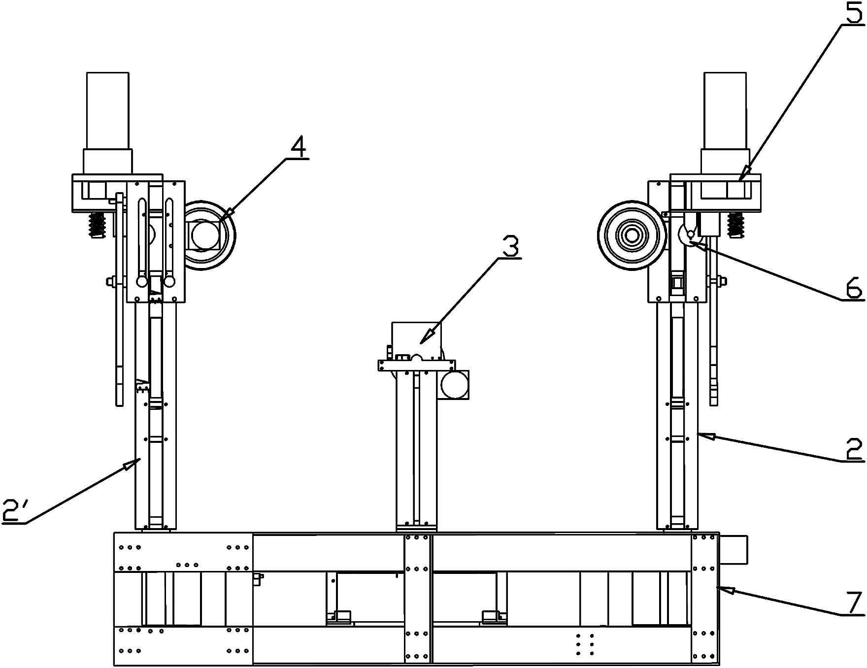
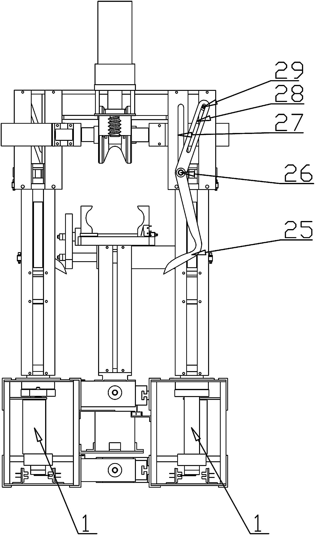
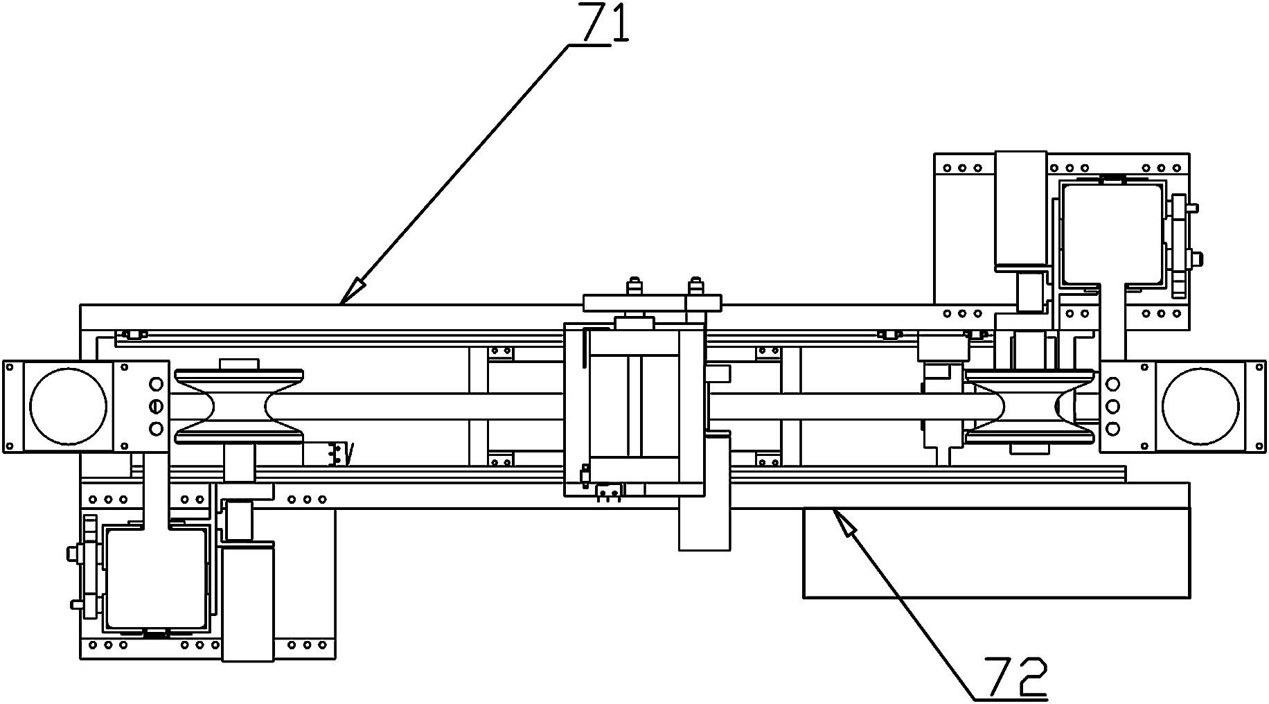
[0036] Such as figure 1 In —3, a transmission line automatic deicing robot, the first traveling box 71 and the second traveling box 72 are connected by a second screw nut mechanism 74, and the screw rod in the second screw nut mechanism 74 is installed on the first traveling box 71 , a first screw nut mechanism 73 is also provided above the second screw nut mechanism 74, and the lower end of the clamping device 3 is connected with the first screw nut mechanism 73 through threads; in this example, in order to reduce friction, part of the screw nut mechanism has adopted Ball screw nut mechanism.

[0037] The first walking box 71 is connected with the first lifting arm device 2 through the rotating device 1 that can make the device installed on it rotate a certain angle, and the second traveling box 72 can make the rotating device installed on it rotate a certain angle. 1 is connected with the second lifting arm device 2';

[0038] The first lifting arm device 2 and / or the seco...


PUM


Abstract

The invention provides a robot for automatically deicing for a power transmission line. A first walking box and a second walking box are connected through a second screw and nut mechanism and a screw of the second screw and nut mechanism is installed on the first walking box; the lower end of a clamping device is connected with a first second screw and nut mechanism through screw threads; the first walking box is connected with a first lifting arm device through a rotation device capable of rotating the device which is installed on the rotation device for a certain angle; the second walking box is connected with a second lifting arm device through a rotation device capable of rotating the device which is installed on the rotation device for a certain angle; the first lifting arm device and the second lifting arm device are all provided with deicing devices and walking devices which are used for driving the whole device to walk; and the first lifting arm device and the second lifting arm device are respectively located at the positions of two ends of the whole walking box and the clamping device is located in the middle. According to the robot for automatically deicing the power transmission line provided by the invention, the deicing on a high-voltage power transmission line is reliably realized and the obstacles can be conveniently and reliably detoured.

Description

Technical field [0001] The invention involves an ice removal device for high -voltage transmission lines, especially an automatic ice removal robot for transmission lines for high -voltage transmission lines. Background technique [0002] With the rapid development of my country's economy, the high -voltage and large -capacity transmission lines have become more and more, and the geographical environment of the line corridor crossing is more complicated. For example, through a large area of ​​reservoirs, lakes, and mountains, it brings many difficulties to the maintenance of the line.my country's current 500VK ultra -high -voltage transmission line is about 270,000 kilometers. In order to ensure its safe and reliable operation, regular detection and maintenance are necessary. [0003] In the severe winter and early spring seasons, the phenomenon of fog and rain and rainfall in my country, Sichuan -Shaanxi area, and two lakes areas, causing an overhead transmission line to cover t...

Claims


Application Information

Patent Timeline
Patent Type & Authority Applications(China)
IPC IPC(8): H02G7/16
Inventor 朱大林张屹艾福洲覃进一韩俊
Owner CHINA THREE GORGES UNIV
Why Eureka
Try Eureka