Pull-type power overhead transmission line deicing device

A technology for overhead power and transmission lines, applied in overhead installation, cable installation, electrical components, etc., can solve problems that threaten power transmission and communication network reliability, cable damage, power transmission system damage, etc., to increase deicing Effect, reasonable structure, novel design effect

Inactive Publication Date: 2018-06-19
ZHENGZHOU TIANSHUN ELECTRONICS TECH CO LTD
View PDF6 Cites 0 Cited by
  • Summary
  • Abstract
  • Description
  • Claims
  • Application Information

AI Technical Summary

Problems solved by technology

In winter, due to the icing problem of the transmission line caused by the climate, the load bearing of the transmission line increases
If the weight of the transmission line covered with ice exceeds the load-bearing range of the transmission line or the tower, it will cause accidents such as disconnection and tower collapse, which will damage the power transmission system and cause great losses to the national economy. Transmission line accidents seriously threaten the reliability of power transmission and communication networks
In order to solve the above problems, some people propose to input a large current to the power grid to increase the temperature of the wires to prevent icing. However, due to the low temperature, it will consume a lot of electric energy to prevent icing, and there are still technical obstacles.
[0003] In the current mechanical deicing machine, the method of cutting with a knife or scraping a pulley is mainly used for deicing. This method is easy to cause great damage to the cable, and the operation of these devices is relatively complicated. The technical requirements for electric maintenance personnel Too high, and for the power transmission cables erected on uneven ground, these devices cannot reach at all

Method used


Image

  • Pull-type power overhead transmission line deicing device
  • Pull-type power overhead transmission line deicing device
  • Pull-type power overhead transmission line deicing device

Examples


Embodiment Construction

[0019] It should be noted that, in the case of no conflict, the embodiments of the present invention and the features in the embodiments can be combined with each other.

[0020] In describing the present invention, it should be understood that the terms "center", "longitudinal", "transverse", "upper", "lower", "front", "rear", "left", "right", " The orientations or positional relationships indicated by "vertical", "horizontal", "top", "bottom", "inner" and "outer" are based on the orientations or positional relationships shown in the drawings, and are only for the convenience of describing the present invention and Simplified descriptions, rather than indicating or implying that the device or element referred to must have a particular orientation, be constructed and operate in a particular orientation, and thus should not be construed as limiting the invention. In addition, the terms "first", "second", etc. are used for descriptive purposes only, and should not be understood ...


PUM


Abstract

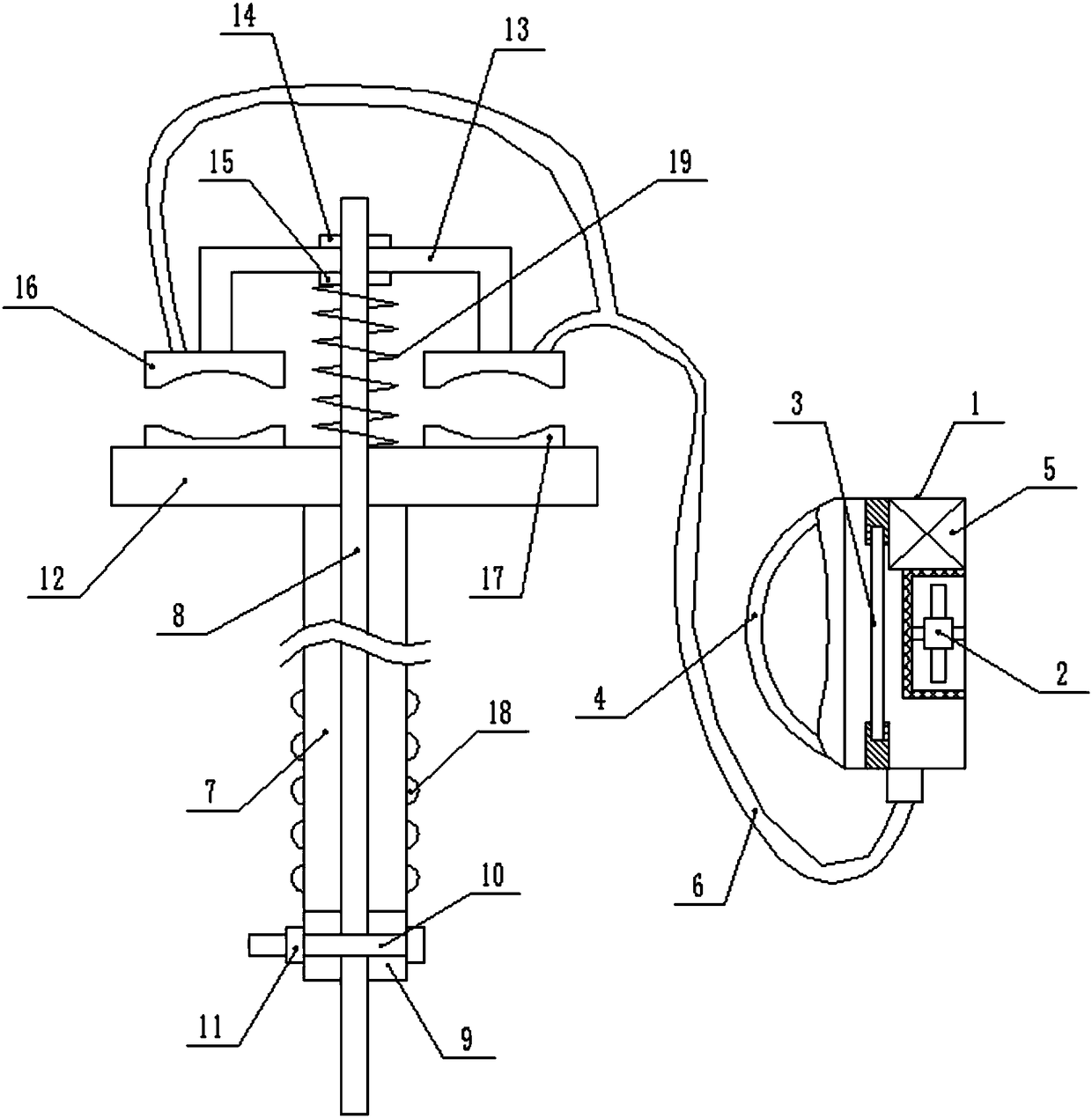
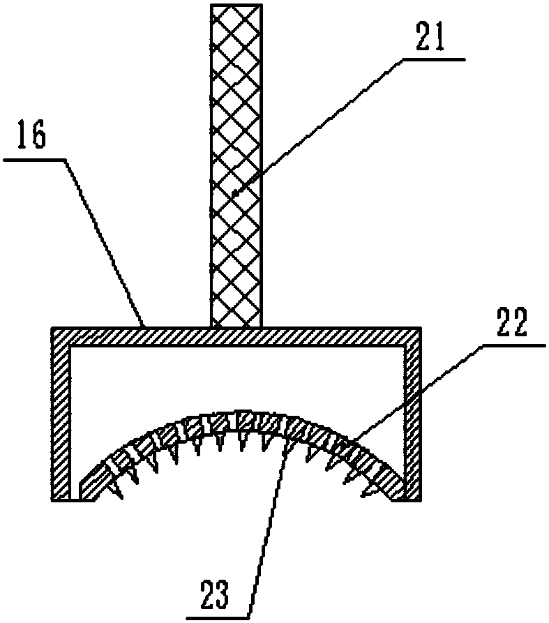
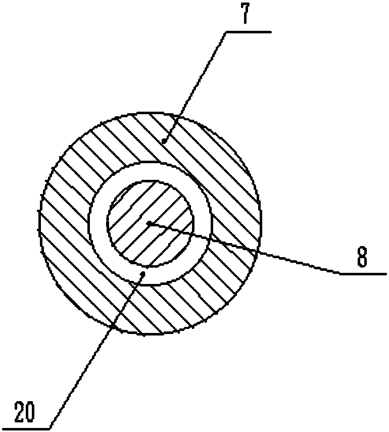
The invention discloses a pull-type power overhead transmission line deicing device, which comprises a back box and a deicing rod. An induced draft fan is installed on the center of the right end inside the back box. A heating wire is installed on the left end inside the back box. The lower end of the back box is connected with a hot air pipe. A fixing plate is installed at the upper end of the deicing rod. A pull rod is installed inside the deicing rod. A clamping rod is installed in the middle of the upper end of the pull rod. A deicing ring is installed at the lower end of the clamping rod.A clamping ring is installed on the inner side of the deicing ring. Deicing teeth are uniformly disposed on the inner side of the clamping ring. A upper nut is installed on the middle of the pull rodat the upper part of the clamping rod. A lower nut is installed on the middle of the pull rod at the lower part of the clamping rod. A fixing block is installed on the lower end of the deicing rod. Afixing screw is installed in the fixing block, passes through the middle portion of the bottom end of the pull rod to be connected with a fixing nut. The push-pull power overhead transmission line deicing device clamps the transmission line by the deicing ring, doubly removes the ice layer on the transmission line, improves an deicing effect, is simple in operation, and satisfies need for deicingtransmission line.

Description

technical field [0001] The invention relates to the technical field of electric power auxiliary equipment, in particular to a pull-type power overhead transmission cable deicing device. Background technique [0002] With the rapid development of my country's economy, there are more and more ultra-high-voltage large-capacity transmission lines. In winter, due to the icing problem of the transmission line caused by the climate, the load bearing of the transmission line increases. If the weight of the transmission line covered with ice exceeds the load-bearing range of the transmission line or the tower, it will cause accidents such as disconnection and tower collapse, which will damage the power transmission system and cause great losses to the national economy. Transmission line accidents seriously threaten the reliability of power transmission and communication networks. In order to solve the above problems, it was proposed to input a larger current to the power grid to in...

Claims


Application Information

Patent Timeline
Patent Type & Authority Applications(China)
IPC IPC(8): H02G7/16
Inventor 李欣
Owner ZHENGZHOU TIANSHUN ELECTRONICS TECH CO LTD
Why Eureka
Try Eureka