Shearing device

A technology of shearing device and shearing mechanism, applied in the field of shearing device of gate, can solve problems such as trouble

Inactive Publication Date: 2012-02-01
HONG FU JIN PRECISION IND (SHENZHEN) CO LTD +1
View PDF2 Cites 2 Cited by
  • Summary
  • Abstract
  • Description
  • Claims
  • Application Information

AI Technical Summary

Problems solved by technology

In this way, the gate cannot be broken off by itself after the plastic part is demoulded, and it can only be cut off manually with scissors and other workpieces, which is very troublesome

Method used


Image

  • Shearing device
  • Shearing device
  • Shearing device

Examples


Embodiment Construction

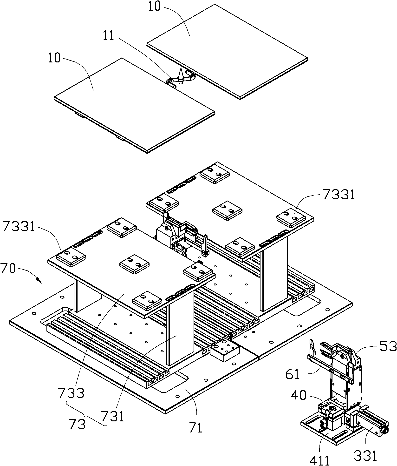
[0026] see figure 1 The shearing device of the present invention is used to shear a gate 11 connected between two plastic parts 10, and its preferred embodiment includes a bottom plate 20, a pushing mechanism 30 fixed on the bottom plate 20, a An adjusting mechanism 40 on the pushing mechanism 30 , a shearing mechanism 50 fixed together with the adjusting mechanism 40 , and an auxiliary adjusting mechanism 60 fixed on the shearing mechanism 50 .

[0027] The plastic part 10 is placed on a base 70 . The base 70 includes a base 71 and a step 73 fixed on the base 71 . The step 73 includes a fixed plate 731 fixed with the base plate 71 and a flat plate 733 fixed on the upper edge of the fixed plate 731 . Five positioning pieces 7331 are installed on the flat plate 733 , and the positioning pieces 7331 are used for positioning the plastic part 10 .

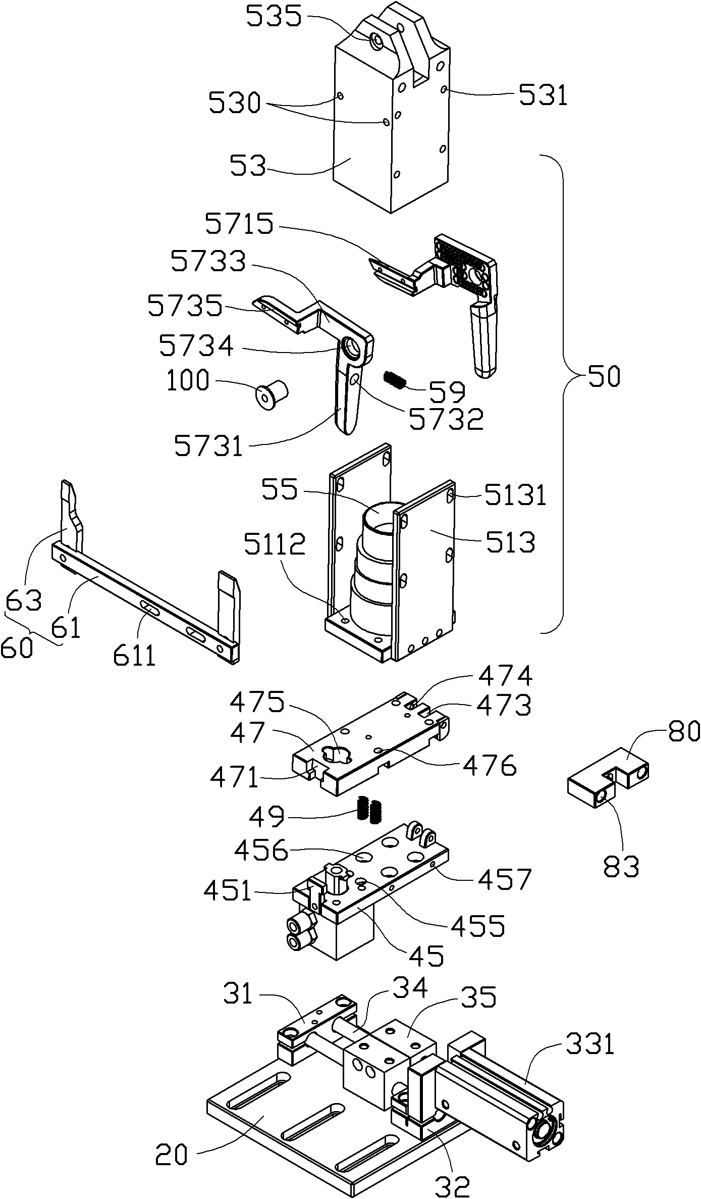
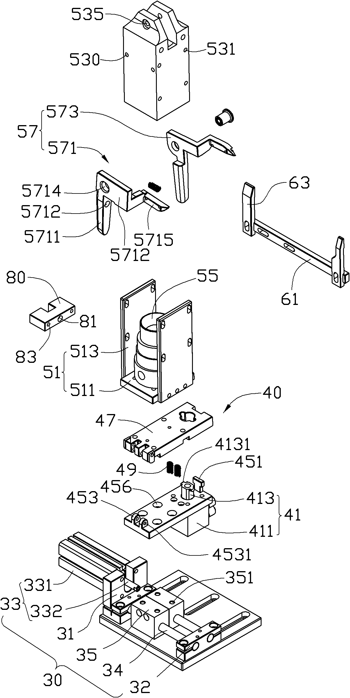
[0028] see figure 2 , image 3 and Figure 4 , the pushing mechanism 30 includes two fixing seats 31, 32 fixed on the base pla...


PUM


Abstract

The invention relates to a shearing device, which is used for shearing a pouring gate of a molding. The shearing device comprises a bottom plate and further comprises a push mechanism and a shear mechanism which are fixed on the bottom plate, wherein the shear mechanism comprises a drive member and a shear member matched with the drive member, the push mechanism is used for pushing the shear mechanism to move along a direction close to the pouring gate so as to make the shear member be aligned to the pouring gate, and the drive member is used for driving the shear member to move so as to shear the pouring gate.

Description

technical field [0001] The invention relates to a shearing device, in particular to a shearing device which can automatically shear the gate of a plastic part. Background technique [0002] Usually, the plastic parts produced by the injection molding machine are made by setting a sprue hole in the mold and injecting materials into the mold through the sprue hole. In this way, a gate will be left on the molded plastic part. The size of the gate is approximately equal to the size of the gate hole. When the size of the plastic part is large, in order to increase the feeding speed, shorten the production time, and improve the work efficiency, the size of the gate hole is usually increased as much as possible, and the gate hole with a large size will inevitably have a large gate hole. mouth. Like this, described sprue all can not be broken off automatically after plastic parts demoulding, can only be cut off by workpieces such as scissors manually, very troublesome. Contents...

Claims


Application Information

Patent Timeline
Patent Type & Authority Applications(China)
IPC IPC(8): B29C45/38
CPCB29C45/382Y10T83/8748
Inventor 姜方李发业谭鹏毕洋岑立恒邹远旭
Owner HONG FU JIN PRECISION IND (SHENZHEN) CO LTD
Why Eureka
Try Eureka