Garden deadwood breaking device

A garden dead branch and support frame technology, which is applied in the field of dead branch breaking devices, can solve the problems of low efficiency of dead branches, easily scratched hands, etc., and achieves the effect of easy handling

Pending Publication Date: 2022-04-12
陈桂连
View PDF7 Cites 0 Cited by
  • Summary
  • Abstract
  • Description
  • Claims
  • Application Information

AI Technical Summary

Problems solved by technology

[0004] In order to overcome the shortcomings of low efficiency and easy scratching of hands by using a cutting knife to cut dead branches manually, the technical problem of the present invention is to provide a garden dead branch breaking device that can quickly cut dead branches

Method used


Image

  • Garden deadwood breaking device
  • Garden deadwood breaking device
  • Garden deadwood breaking device

Examples


Embodiment 1

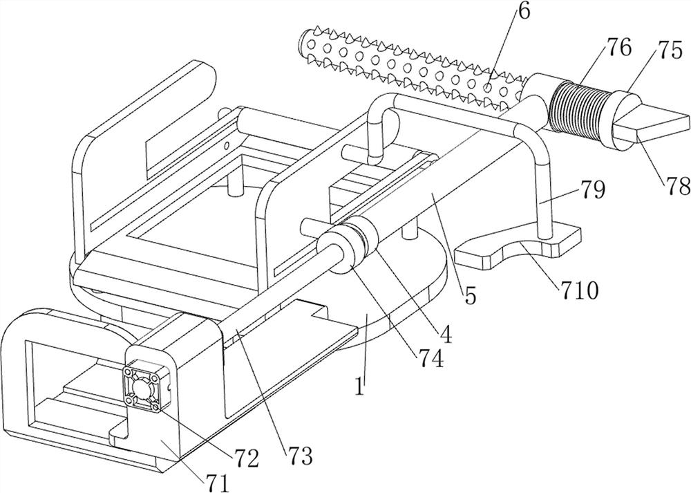
[0027] A garden dead branch interrupting device, such as Figure 1-4 As shown, it includes a base plate 1, a support column 2, a workbench 3, a first support frame 4, a first movable rod 5, a breaking rod 6, a pushing mechanism 7, a transmission mechanism 8 and a cutting mechanism 9, and the right side of the top of the base plate 1 Four support columns 2 are evenly arranged, a workbench 3 is arranged between the tops of the support columns 2, a first support frame 4 is provided on the front side of the workbench 3, and a first movable rod 5 is slidingly provided on the first support frame 4, The sliding type on the right side of the first movable rod 5 is provided with a breaking rod 6, and the front side of the top of the base plate 1 is provided with a pushing mechanism 7, and the pushing mechanism 7 cooperates with the first movable rod 5, and the workbench 3 is provided with a transmission mechanism 8, and the workbench 3. A cutting mechanism 9 is provided on the top, and...

Embodiment 2

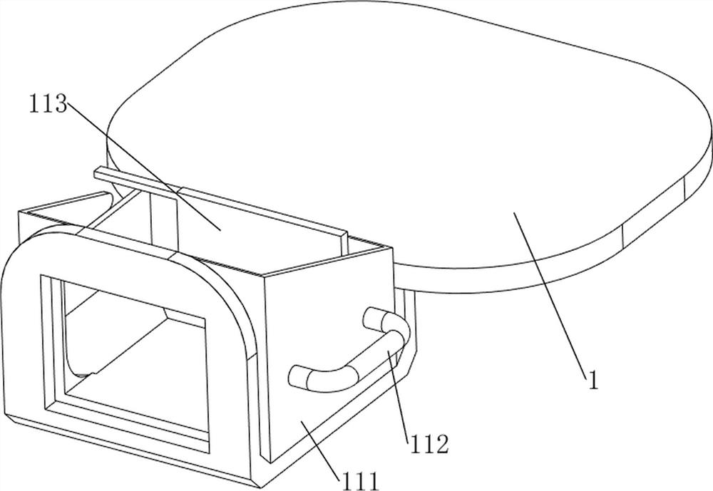
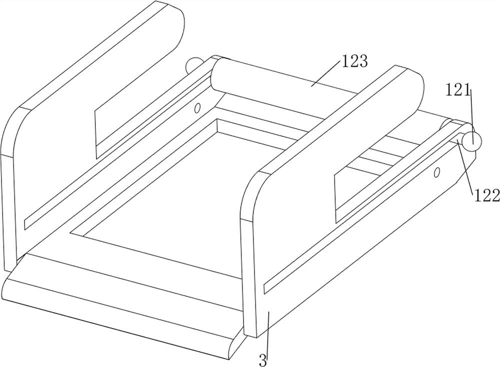
[0036] On the basis of Example 1, such as figure 1 and Figure 5-7 As shown, a moving mechanism 10 is also included. The moving mechanism 10 includes a second support plate 101, a roller 102, a handle 103 and a fifth support frame 104. The right side of the top of the bottom plate 1 is provided with a second support plate 101, and the second support plate 101 is provided with rollers 102 symmetrically rotating forward and backward, a handle 103 is provided on the left side of the second support plate 101 , and a fifth support frame 104 is provided symmetrically front and rear at the bottom of the handle 103 .

[0037] When people need to push the interrupting device to a suitable position, people can first pull up the handle 103 to drive the fifth support frame 104 to rotate upwards so that it is no longer in contact with the ground. At this time, people move the handle 103 to drive the rollers 102 to rotate. Then drive the base plate 1 to move, and the rollers 102 rotate to ...


PUM


Abstract

The invention relates to a deadwood breaking device, in particular to a garden deadwood breaking device. The technical problem of the invention is to provide the garden deadwood breaking device capable of quickly cutting deadwood. According to the technical scheme, the garden deadwood breaking device comprises a bottom plate, supporting columns, a workbench, a first supporting frame, a first movable rod, a breaking rod, a pushing mechanism, a conveying mechanism and a cutting mechanism, the four supporting columns are evenly arranged on one side of the top of the bottom plate, the workbench is arranged between the tops of the supporting columns, and the first supporting frame is arranged on one side of the workbench; and a first movable rod is slidably arranged on the first supporting frame, a breaking rod is slidably arranged on one side of the first movable rod, a pushing mechanism is arranged on the other side of the top of the bottom plate, and the pushing mechanism is matched with the first movable rod. The device has the beneficial effects that the transmission mechanism works to drive deadwood to move leftwards for cutting, and manual pushing is not needed.

Description

technical field [0001] The invention relates to a dead branch breaking device, in particular to a garden dead branch breaking device. Background technique [0002] Dead branches refer to dry branches. With the continuous improvement of Yunnan's urbanization level, the area of ​​urban green space continues to expand, and the total amount of garden plant waste such as dead branches and leaves and branch prunings is increasing. Dead branches can be made into original ecology by DIY The level of handicraft makes it turn waste into treasure. The dead branches falling from the tree are too large to be bundled and transported. They need to be cut simply, which is more convenient for people to make handicrafts. Branches are cut, and manual use of cutting knives to cut dead branches is inefficient and easily scratches hands. [0003] Therefore, need to design a kind of garden dead branch interrupting device that can cut dead branch fast. Contents of the invention [0004] In orde...

Claims


Application Information

Patent Timeline
Patent Type & Authority Applications(China)
IPC IPC(8): B27C5/02B27C5/06B27G3/00
Inventor 陈桂连
Owner 陈桂连
Why Eureka
Try Eureka