High current silicon pile cutting machine

A high-current, cutting machine technology, applied in the field of high-current silicon stack cutting machine, can solve the problems of large lead length error, high labor intensity, low efficiency, etc., and achieve the effect of low labor intensity, simple design and high efficiency

Active Publication Date: 2017-07-25
江苏皋鑫电子有限公司
View PDF6 Cites 0 Cited by
  • Summary
  • Abstract
  • Description
  • Claims
  • Application Information

AI Technical Summary

Problems solved by technology

[0002] In the past, the pin size of the high-current silicon stack was required by the customer, and it needed to be cut to meet the customer's needs; however, the cutting of the pins was completely dependent on manual cutting at both ends on the wire cutting machine, which was labor-intensive, low in efficiency, and the lead length error was large.

Method used


Image

  • High current silicon pile cutting machine
  • High current silicon pile cutting machine

Examples


Embodiment Construction

[0012] In order to further illustrate the present invention, introduce below in conjunction with accompanying drawing of description:

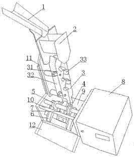
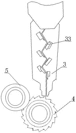
[0013] With reference to the accompanying drawings, the high-current silicon stack cutting machine includes a feeding screen 1, a feeding hopper 2, a correcting and unloading mechanism 3, a ratchet 4, a knife wheel 5, a waste outlet 6, a pressing plate 7, a motor, a control box 8 and a machine. Seat 9 and machine base 9 are U-shaped, and one side of the upper end of machine base 9 is connected by cross bar 10, and one side of cross bar 10 has cutter wheel shaft installed in the middle of machine base 9, two cutter wheels 5 are housed on the cutter wheel shaft, and the cutter wheel shaft There is a ratchet shaft installed in the middle of the machine base obliquely below. Two ratchets are installed on the ratchet shaft. A cross brace is installed at the lower end of the cross bar 10. A pressure plate 7 is installed in the middle of the cross bra...


PUM


Abstract

The invention relates to a heavy current silicon stack foot cutting machine comprising a feeding sieve, a charging hopper, a rectifying discharging mechanism, ratchets, cutter wheels, waste material outlets, a press plate, a motor and a control box as well as a machine base. The machine base is U-shaped; one side of the upper end of the machine base is connected with a cross rod; one side of the cross rod is provided with a cutting wheel shaft disposed in the middle of the machine base; two cutting wheels are arranged on the cutting wheel shaft; a ratchet shaft slantwise under the cutting wheel shaft is placed in the middle of the machine base; two ratchets are arranged on the ratchet shaft; the lower end of the cross rod is provided with a transverse support; the press plate is mounted in the middle of the transverse support; the press plate is arranged over the ratchets and between the two cutting wheels; the rectifying discharging mechanism is arranged over the ratchets; the charging hopper is arranged over the rectifying discharging mechanism; the feeding sieve over the charging hopper is slantwise arranged on the top end of a side plate; the finished product outlet under the ratchets is formed on the upper end of the machine base; and the control box is mounted on one side of the machine base. The heavy current silicon stack foot cutting machine is advantaged by simple design, convenient use, free of manual cutting work, small labor intensity, high efficiency, great lead length precision and satisfaction to client demands.

Description

technical field [0001] The invention relates to a silicon pile cutting device, in particular to a high-current silicon pile cutting machine. Background technique [0002] In the past, the pin size of the high-current silicon stack was required by the customer, and it needed to be cut to meet the customer's needs; however, the cutting of the pins was completely dependent on manual cutting at both ends on the wire cutting machine, which was labor-intensive, low in efficiency, and the lead length error was large. Contents of the invention [0003] In order to solve the above problems, the present invention proposes a high-current silicon pile cutting machine, which is simple in design, easy to use, does not need manual cutting, has low labor intensity, high efficiency, and high precision of lead wire length. [0004] In order to achieve the above-mentioned purpose of the invention, the present invention proposes the following technical solutions: [0005] High-current silico...

Claims


Application Information

Patent Timeline
Patent Type & Authority Patents(China)
IPC IPC(8): B21F11/00B21F23/00B21F1/02
Inventor 倪绍荣
Owner 江苏皋鑫电子有限公司
Why Eureka
Try Eureka