System and method for controlling DMA data transfer

a data transfer and control system technology, applied in the field of data transfer control systems, can solve the problems of increasing processing overhead, limited functional flexibility of dmacs with hardware-oriented design, and failing to provide the necessary features of other applications

Inactive Publication Date: 2005-10-06
FUJITSU LTD
View PDF6 Cites 99 Cited by
  • Summary
  • Abstract
  • Description
  • Claims
  • Application Information

AI Technical Summary

Benefits of technology

[0016] In view of the foregoing, it is an object of the present invention to provide a data transfer control system, a DMA controller, and a DMA control method that can change the way of DMA transfers to meet the requirements of each application.

Problems solved by technology

DMACs with hardware-oriented design, however, are limited in terms of functional flexibility.
Some of their functions may be superfluous in a certain class of applications, while they may fail to provide necessary features in other applications.
The penalty is an increased processing overhead, which is likely to result in a performance degradation.
Cost requirements and power consumption requirements of a system impose a limit on DMAC designs.
For these reasons, DMACs are only allowed to have relatively simple addressing capabilities, and it is therefore difficult for ordinary DMACs to realize DMA transfers with sophisticated addressing patterns.
Some existing DMACs support special addressing, but most of them are designed for particular applications and often inappropriate for other applications.
As described above, existing hardware-implemented DMACs are so simple and limited in their flexibility that they are unable to provide the data transfer patterns required in actual applications.
This method, however, consumes much of the computation time of the main processor, thus leading to degradation of system performance.
Although the sub-processor approach offers higher flexibility, it has an obvious disadvantage in transfer speeds.
The cost is another problem of this approach, because a general-purpose processor requires a greater amount of circuit resources than an ordinary single-purpose DMAC does.
The problem is, however, that the sub-processor has to fetch instructions as well as to read and write data through the same port of the DPRAM, thus slowing down the execution speed.
If the sub-processor was slow, a consequent delay of DMA data transfers would hamper the main processor from proceeding to the next task.

Method used


Image

  • System and method for controlling DMA data transfer
  • System and method for controlling DMA data transfer
  • System and method for controlling DMA data transfer

Examples


first embodiment

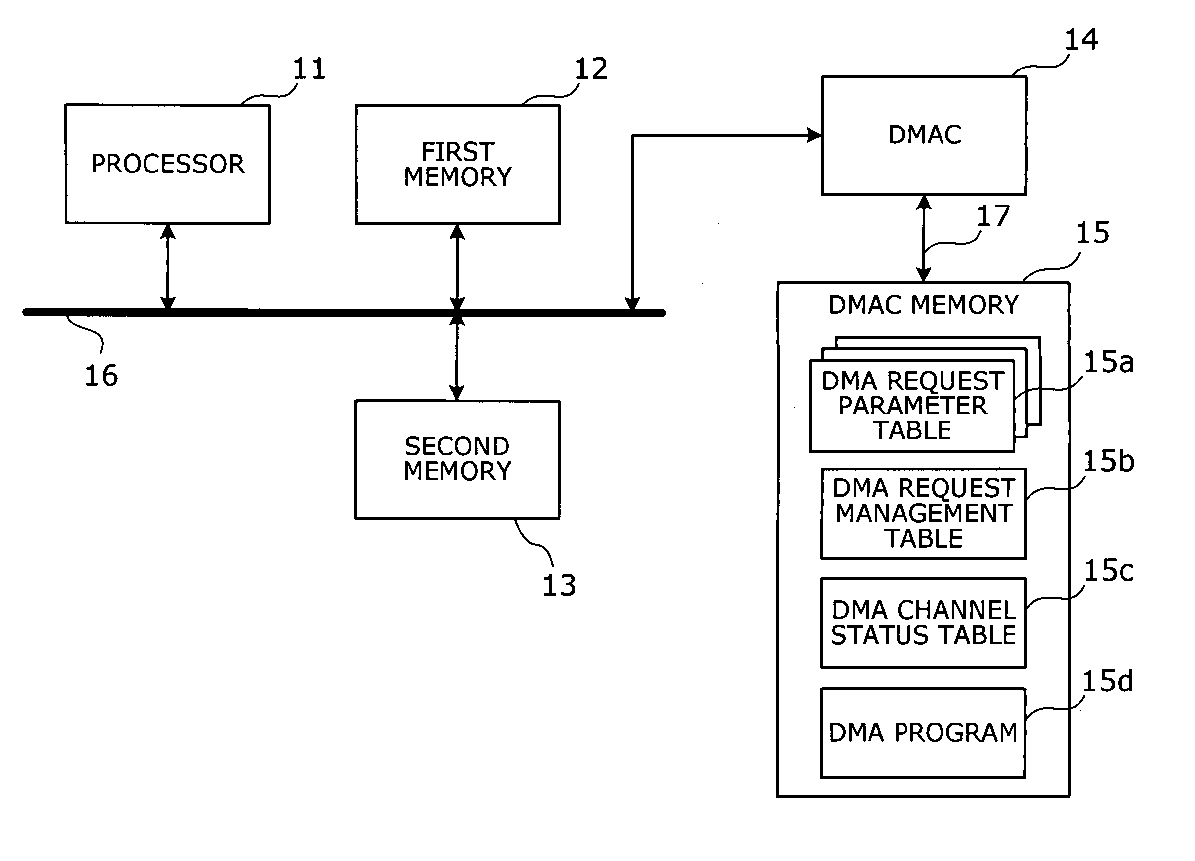
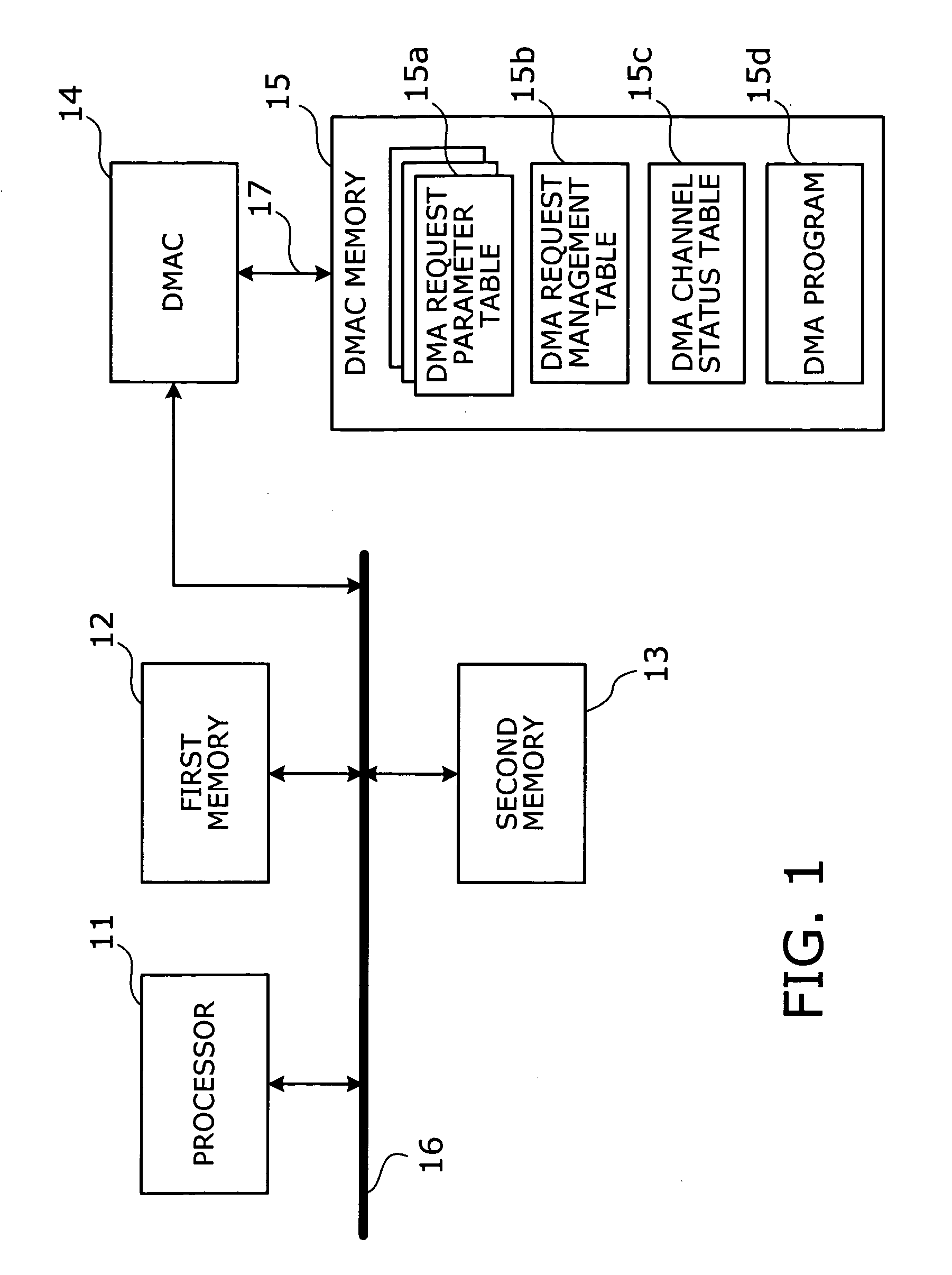
[0061]FIG. 1 shows an example system configuration according to a first embodiment of the present invention. This embodiment represents the basic concept of the invention. In the illustrated system, a processor 11 and first and second memories 12 and 13 are connected to a DMA controller (DMAC) 14 via a bus 16. A DMAC memory 15 is connected to the DMAC 14 through a dedicated bus 17. The processor 11 controls the entire system, using the first and second memories 12 and 13 to store data for system operation. The DMAC 14 is a circuit that controls data transfer between specified memory areas. In response to a DMA request, the DMAC 14 executes a data transfer according to a DMA program 15d and related data stored in the DMAC memory 15. The DMAC 14 is a programmable circuit specially designed for DMA control, which includes an instruction decoder that decodes instructions of the DMA program 15d, and an address generator circuit that produces read and write address signals for use in DMA ...

second embodiment

[0087] This section describes a second embodiment of the present invention, which allows the number of DMA channels to be varied easily. Generally speaking, different system applications require different numbers of DMA channels. However, ordinary hard-wired DMA functions can only provide a fixed number of channels. This means that, in some cases, existing DMAC devices offer more DMA channels than required, or in other cases, they are unable to provide a required number of channels, thus imposing an increased load on the host processor in managing many DMA requests with an insufficient number of channels.

[0088] The second embodiment of the present invention offers multi-channel DMA transfer capabilities by using a DMA request management table of the first embodiment to control each DMA channel, as well as newly employing a channel management table to manage a plurality of DMA request management tables created in a DMAC memory area. Within the limit of memory capacity, the DMAC can ...

third embodiment

[0110] This section describes a third embodiment of the present invention, which focuses on how a host processor is involved in the control of a DMAC. FIG. 10 shows an example system configuration according to the third embodiment of the invention. In this system, a host processor 21 is connected to a first memory 22, a DMAC 24, and a DMAC memory 25 through a first bus 26. The host processor 21 is also coupled directly to the DMAC 24 through a special bus 28. A second memory 23 is disposed on another bus 27, and the first memory 22 and DMAC 24 are coupled to this second memory 23 via that second bus 27. The DMAC 24 is further coupled to a DMAC memory 25 via a bus 29. The special bus 28 is used to send and receive control signals including a reset signal and transfer completion signal, allowing the host processor 21 to make access to the DMAC memory 25 so as to change DMA programs and control DMA transfer timings.

[0111] Conventional hardware-implemented DMACs cannot change their fun...


PUM


Abstract

A data transfer control system that can change the way of DMA transfers to meet the requirements of each application. The data transfer control system includes a DMA controller (DMAC) and a DMAC memory dedicated for DMA control purposes. The DMAC performs DMA transfers according to a DMA program stored in the DMAC memory. Each time a new DMA request is received, the DMAC saves its parameters in a DMA request parameter table, and each DMA request parameter table is registered with a DMA request management table. In this way, the received DMA requests are queued in the DMA request management table. They are executed in a first-in first-out fashion. The progress of ongoing DMA transfers are managed in a DMA channel status table disposed for each DMA channel.

Description

[0001] This application is a continuing application, filed under 35 U.S.C. §111(a), of International Application PCT / JP2003 / 002608, filed Mar. 5, 2003.BACKGROUND OF THE INVENTION [0002] 1. Field of the Invention [0003] The present invention relates to a data transfer control system, a direct memory access (DMA) controller, and a DMA data transfer method. More particularly, the present invention relates to a data transfer control system, a DMA controller, and a DMA data transfer method that can change the way of data transfers. [0004] 2. Description of the Related Art [0005] There are computer systems that need to process a large amount of data objects while inputting and outputting them at very high speeds. To achieve the purpose, those systems often employ a special data transfer mechanism, other than the main processor for general data processing. This mechanism is known as a direct memory access (DMA) controller. The DMA controller, or DMAC, normally works independently of the ma...

Claims


Application Information

Patent Timeline
Patent Type & Authority Applications(United States)
IPC IPC(8): G06F13/28
CPCG06F13/28
Inventor TANAKA, RYUTATSURUTA, TORUTANAKA, RITSUKOKUMAMOTO, NORICHIKA
Owner FUJITSU LTD
Why Eureka
Try Eureka