Three-way electric switching valve

An electric switching, three-way technology, used in multi-way valves, valve details, valve devices, etc., can solve problems such as inability to achieve

Inactive Publication Date: 2012-02-01
全龙浩
View PDF0 Cites 0 Cited by
  • Summary
  • Abstract
  • Description
  • Claims
  • Application Information

AI Technical Summary

Problems solved by technology

[0002] In recent years, due to the continuous reform of the country's winter heating policy, the technology of temperature control valves has made great progress, but there are still many technical gaps in the application: people sometimes hope that one valve can alternately heat two rooms, for example, during the day a If there are people in the room, it should heat the room A, and if there is no one in the room B, it should stop heating the room B. Automatic heating; but existing technology can not achieve this function

Method used


Image

  • Three-way electric switching valve
  • Three-way electric switching valve

Examples


Embodiment Construction

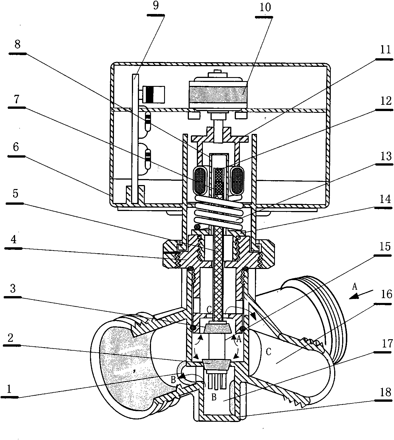
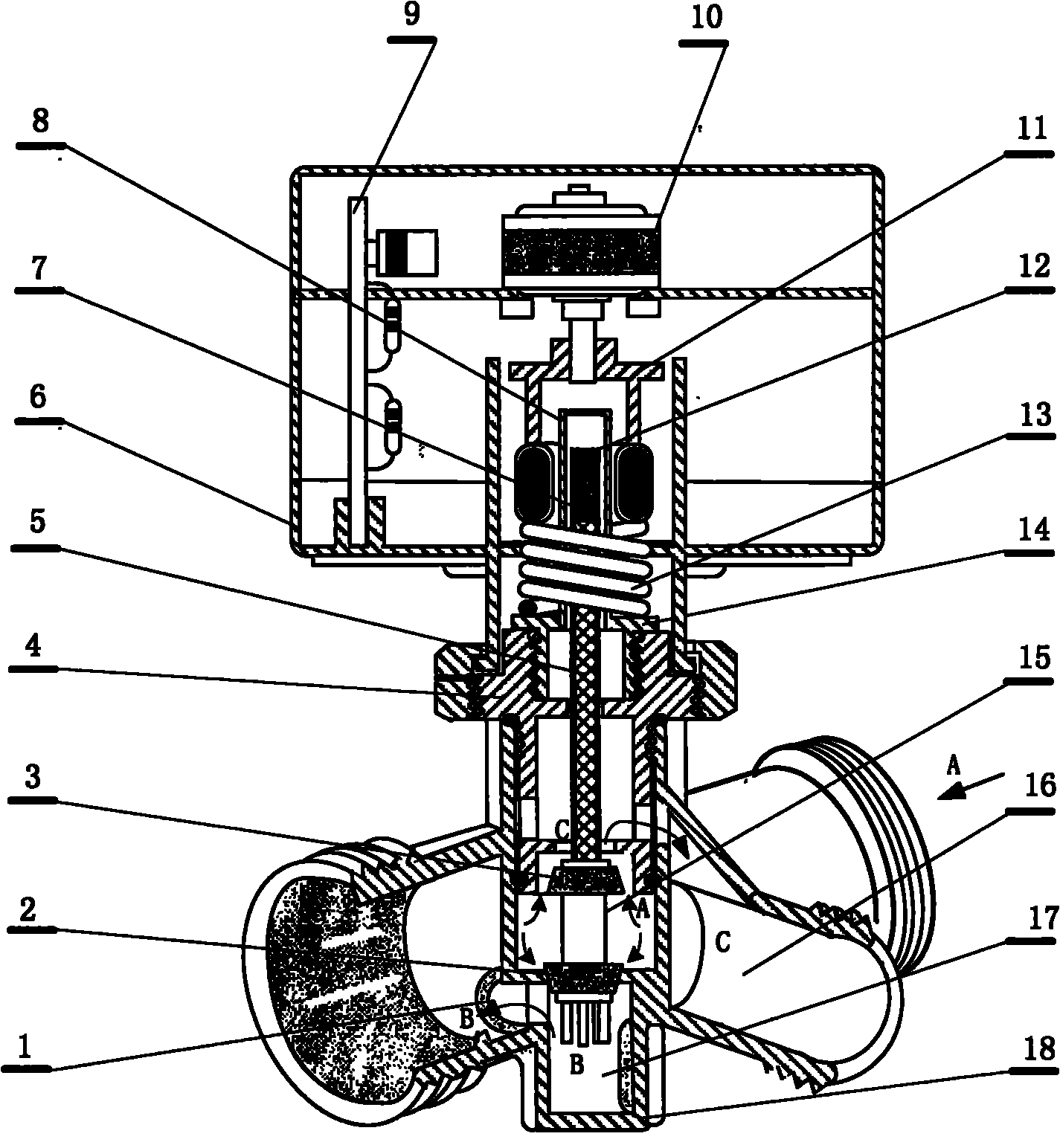
[0008] The embodiment is the application of the present invention in the heating system. The system is composed of a temperature and time adjustment controller and a three-way electric switching valve. At the user's heating entrance, the two outlets are respectively connected to the two rooms that need to be heated in different periods. In the drawings, water outlet B (1), lower piston (2), upper piston (3), valve cavity cover (4), valve core rod (5), protection box (6), magnetic ring assembly (7), Magnetic column cover (8), control board (9), motor (10), linkage (11), magnetic column assembly (12), return spring (13), valve core cover (14), piston rod (15) , water outlet C (16), water outlet B (17), and valve body (18); in the figure, the water flow enters the A cavity in the valve from the A port, and the A cavity is controlled by the piston to switch to the B water flow or the C water flow. Output from port B or port C; the upper end of the piston rod (15) is covered with ...


PUM


Abstract

The invention relates to a three-way electric switching valve, and belongs to the technical field of water heating valves. The switching valve is characterized in that the heat medium of the three-way electric switching valve enters an cavity A in the valve body from a port A, the cavity A is controlled by a piston so as to switch a waterflow B between a waterflow C.

Description

technical field [0001] A three-way electric switching valve belongs to the technical field of plumbing valve control. Background technique [0002] In recent years, due to the continuous reform of the country's winter heating policy, the technology of temperature control valves has made great progress, but there are still many technical gaps in the application: people sometimes hope that one valve can alternately heat two rooms, for example, during the day a If there are people in the room, the heating should be given to room A, and if there is no one in room B, the heating to room B should be stopped. Automatic heating; but existing technology cannot realize this function. Contents of the invention [0003] The purpose of the present invention is to provide a technical proposal of a three-way electric switching valve. [0004] The technical scheme of the present invention is realized in this way. The system is composed of a temperature and time adjustment controller and...

Claims


Application Information

Patent Timeline
Patent Type & Authority Applications(China)
IPC IPC(8): F16K11/044F16K31/02
Inventor 全龙浩王建华
Owner 全龙浩
Why Eureka
Try Eureka