Circuit breaker, in particular for low voltages

A circuit breaker and low-voltage technology, especially used in the field of low-voltage circuit breakers, can solve problems such as inability to visually identify, and achieve the effect of simplifying the equipment of circuit breakers

Inactive Publication Date: 2012-02-01
SIEMENS AG
View PDF3 Cites 11 Cited by
  • Summary
  • Abstract
  • Description
  • Claims
  • Application Information

AI Technical Summary

Problems solved by technology

Also when screwing in the cylinder lock (or cylinder lock unit) it is mostly ...

Method used


Image

  • Circuit breaker, in particular for low voltages
  • Circuit breaker, in particular for low voltages
  • Circuit breaker, in particular for low voltages

Examples


Embodiment Construction

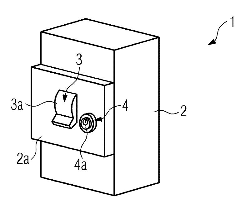
[0017] figure 1 A circuit breaker for low voltage (referred to below as switch 1 ) is shown, which has a housing 2 with a cover 2 a from which a handle 3 in the form of a rocker 3 a protrudes. The pivot lever 3 a can be pivoted manually from the on position to the off position and indicates via its corresponding lever position whether the circuit breaker 1 is switched on or off. The rocker 3 a opens and closes switching contacts, not shown, through which current flows through the switch 1 .

[0018] A locking device 4 in the form of a cylinder lock 4a, which in its locked position prevents the switch 1 from being switched on, is located next to the rocker 3a. The rocker 3 a and the cylinder lock 4 a extend outwards through the cover 2 a and are accessible to the operator.

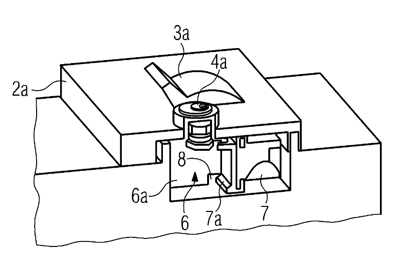
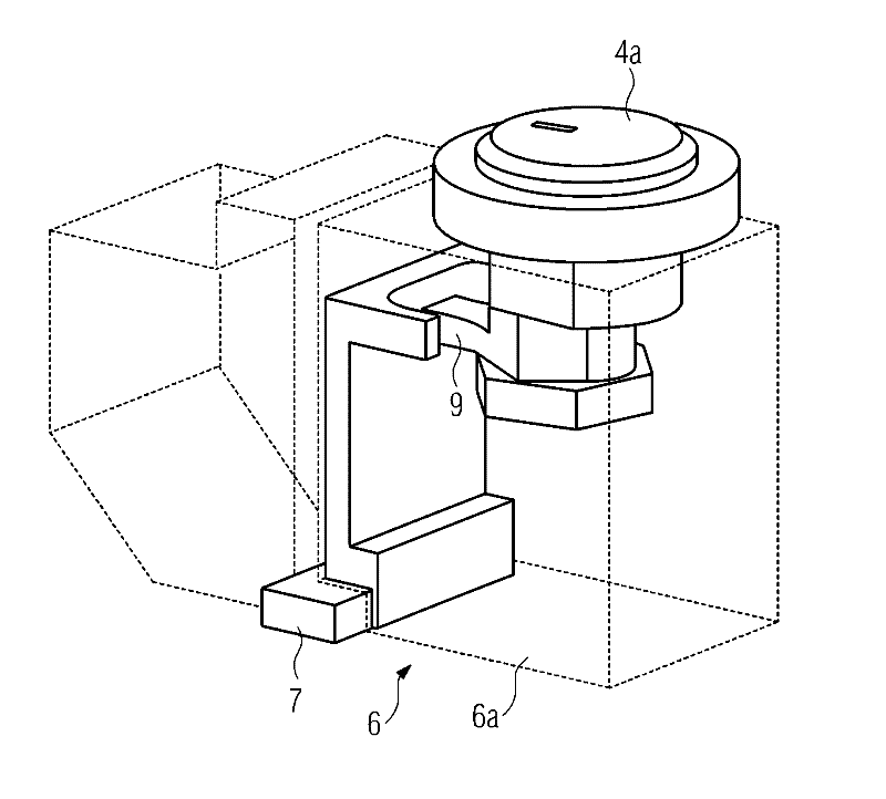
[0019] exist figure 2 shown in partial section in accordance with figure 1 switch 1, and the line of sight is towards the cylinder lock 4a, which belongs to the cylinder lock unit 6a (interlock unit 6)...


PUM


Abstract

The circuit breaker (1) used for low voltages has a housing (2) and a pivoting handle (3) that extends from housing, and indicates the ON/OFF position of the circuit breaker (1). And a locking device is provided (4), the circuit breaker blocks change of switch state at a locking position. In order to mount the locking device (4) with very low cost and without tools, it is suggested that the locking device (4) is formed by a locking portion (4a) and in a gap (6b) of the housing (2), the gap is disposed beside the handle (3) and connected with the handle via a through-hole (8), the locking portion (4a) has a slider (7a) that is latched in through-hole (8) into which a portion of handle (3) is pushed such that pivoting of handle (3)is blocked.

Description

technical field [0001] The invention relates to a circuit breaker, in particular for low voltages, as stated in the preamble of claim 1 . Background technique [0002] It is known to use cylinder locks to interlock (or lock) low-voltage circuit breakers in the switching state. To retrofit the circuit breaker, the cylinder lock and the associated mechanism are screwed directly into the additional cover of the housing. Many faults can arise here. For example, for mounting, a cutout is required in the cover, which has to be opened by the user, which tends to lead to deviations, since the cutting position is not clearly defined here. In addition, when the circuit breaker is interlocked, if the circuit breaker is not unlocked, additional accessories cannot be equipped, because the attached cover can only be removed in the unlocked state. Furthermore, when screwing in the cylinder lock (or cylinder lock unit), it is often not possible to visually recognize whether the circuit b...

Claims


Application Information

Patent Timeline
IPC IPC(8): H01H9/28
CPCH01H9/285H01H71/1054H01H9/223
Inventor A.斯佩特
Owner SIEMENS AG
Why Eureka
Try Eureka