Gas-liquid two-phase helical flow generating device in pipeline

A generating device and spiral flow technology, which is applied in the pipeline system, gas/liquid distribution and storage, mechanical equipment, etc., can solve problems such as insignificant spiral effect, unsuitable spiral flow, and unsolved installation problems, etc., to achieve a wide range of applications , good spiral effect and simple structure

Inactive Publication Date: 2012-02-08
CHANGZHOU UNIV +1
View PDF9 Cites 8 Cited by
  • Summary
  • Abstract
  • Description
  • Claims
  • Application Information

AI Technical Summary

Problems solved by technology

But this invention does not solve the installation problem, the spiral effect is not obvious, and it is not suitable for the generation of gas-liquid two-phase spiral flow

Method used


Image

  • Gas-liquid two-phase helical flow generating device in pipeline
  • Gas-liquid two-phase helical flow generating device in pipeline
  • Gas-liquid two-phase helical flow generating device in pipeline

Examples


Embodiment Construction

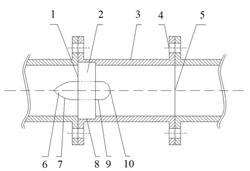
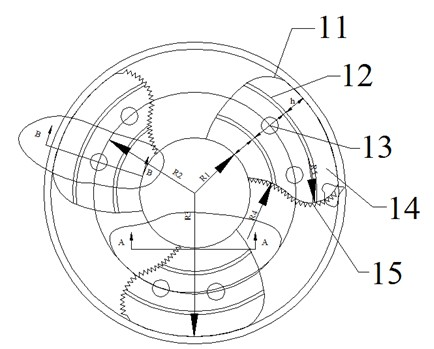
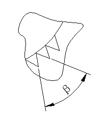
[0021] Such as figure 1 , 2 As shown, the present invention is made up of helical flow generator 2 and installation pipe section. The helical flow generator includes a fixed ring 8, an impeller 11 and a guide body 6; the impeller 11 is composed of three identical blades 14, the fixed ring 8 and the blades 14 are connected by welding, and the overall external profile of the blade 14 is a propeller blade shape , the three blades are evenly welded on the guide body at intervals of 120°, such as Figure 4 As shown, the angle α between the plane of the blade 14 and the cross section of the guide body 6 is 20°. The blades are provided with deflectors 12, flow holes 13 and serrated trailing edges 15; the deflectors 12 are arc-shaped, and are evenly distributed on the blades 14 with the deflector 6 as the center. The distance h is all equal, the height of the deflector plate 12 is 5mm, and the distribution number on each blade 14 is 2, such as Figure 5 As shown, the angle γ betwe...


PUM


Abstract

The invention discloses a gas-liquid two-phase helical flow generating device in a pipeline, which comprises a helical flow generator (2) and an installation pipe section, wherein the helical flow generator (2) comprises a flow guide body (6), a fixed ring (8) and three same blades (14); the whole outer outline of the blades (14) is shaped as a helical propeller blade, the inner sides of the blades are uniformly fixed on the flow guide body (6) at intervals, the outer sides of the blades are fixed on the inner side of the fixed ring (8); an included angle alpha exists between the blades (14) and the cross section of the flow guide body (6); arc flow guide plates (!2) uniformly arranged by using the flow guide body (6) as a center are arranged on the blades (14); and the installation pipe section comprises a pipe housing (3), and the helical flow generator (2) is arranged on the inlet end of the installation pipe section. The gas-liquid two-phase helical flow generating device has the advantages of good helical effect, low fluid state attenuation speed and wide applicable range.

Description

technical field [0001] The invention belongs to a gas-liquid two-phase fluid transmission device in a pipeline, in particular to a pipeline spinning device for transmitting gas-liquid two-phase fluid. Background technique [0002] Spiral flow is a flow form with a rotating flow field. It has a wide range of industrial applications, including hydraulic engineering and mechanical processing. At the same time, spiral flow technology has also entered the field of people's daily life, such as spiral flow energy-saving gas stoves. Since spiral flow has such a wide range of applications, the conditions for its generation are very critical. Generally speaking, there are three conventional methods for generating spiral flow: tangential flow, installation of deflectors, and rotating pipes. [0003] The helical flow generating device with deflector type is to generate helical flow by changing the boundary conditions of the water flow in the circular pipe, that is, a number of fixed g...

Claims


Application Information

Patent Timeline
Patent Type & Authority Applications(China)
IPC IPC(8): F17D1/20
Inventor 王树立饶永超金海鸥周诗岽李恩田
Owner CHANGZHOU UNIV
Why Eureka
Try Eureka