Circular cone type spiral flow generator

A generator and helical flow technology, applied in the pipeline system, mechanical equipment, gas/liquid distribution and storage, etc., can solve the problems of low strength, difficult processing, unfavorable fixation, etc., and achieve high helical strength, good helical effect, The effect of novel structure

Active Publication Date: 2013-02-13
江苏卓燃知识产权运营有限公司
View PDF6 Cites 6 Cited by
  • Summary
  • Abstract
  • Description
  • Claims
  • Application Information

AI Technical Summary

Problems solved by technology

This device can generate spiral flow and improve fluid delivery efficiency, but this device also has some disadvantages: it is inconvenient to install, and the connection method between the round steel pipe and the pipeline is not involved in the description of the patent; in addition, the strength is not high, and the patent is four The blades are set on the inner wall, and when the slurry flows through, it will have a great impact on the blades
This invention can make the mixed fluid flow in the pipeline in a spiral and layered manner, which is suitable for the transportation of paraffin and scale deposits in the pipeline, and is also conducive to cleaning wax deposits, but this invention also has obvious defects: ① The spiral blades are thin, which is not conducive to fixing
The intermediate body is fixed by the spiral blade, and when a solid fluid such as slurry passes through, it will cause a large impact on the intermediate body, which may damage the blade
②This device is closed, and the internal processing is difficult, which is not conducive to the actual promotion
For now, although there are many spiral flow generating devices, there are generally problems such as poor spiral effect, low impact strength and difficult processing. Therefore, the above methods cannot meet the requirements.

Method used


Image

  • Circular cone type spiral flow generator
  • Circular cone type spiral flow generator
  • Circular cone type spiral flow generator

Examples


Embodiment Construction

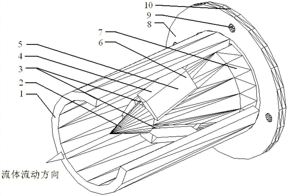
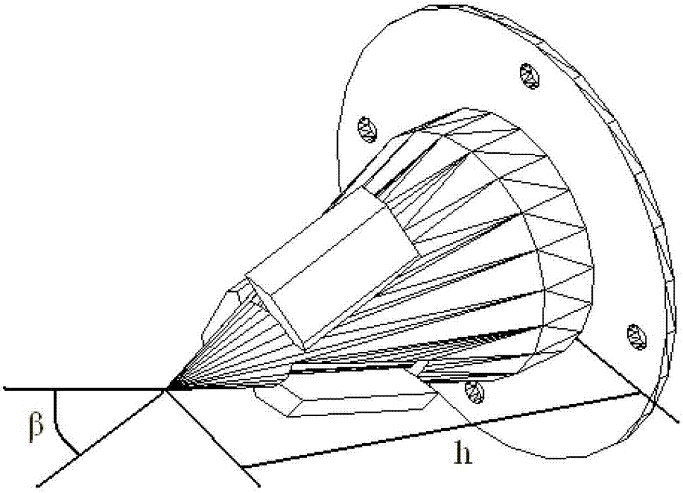
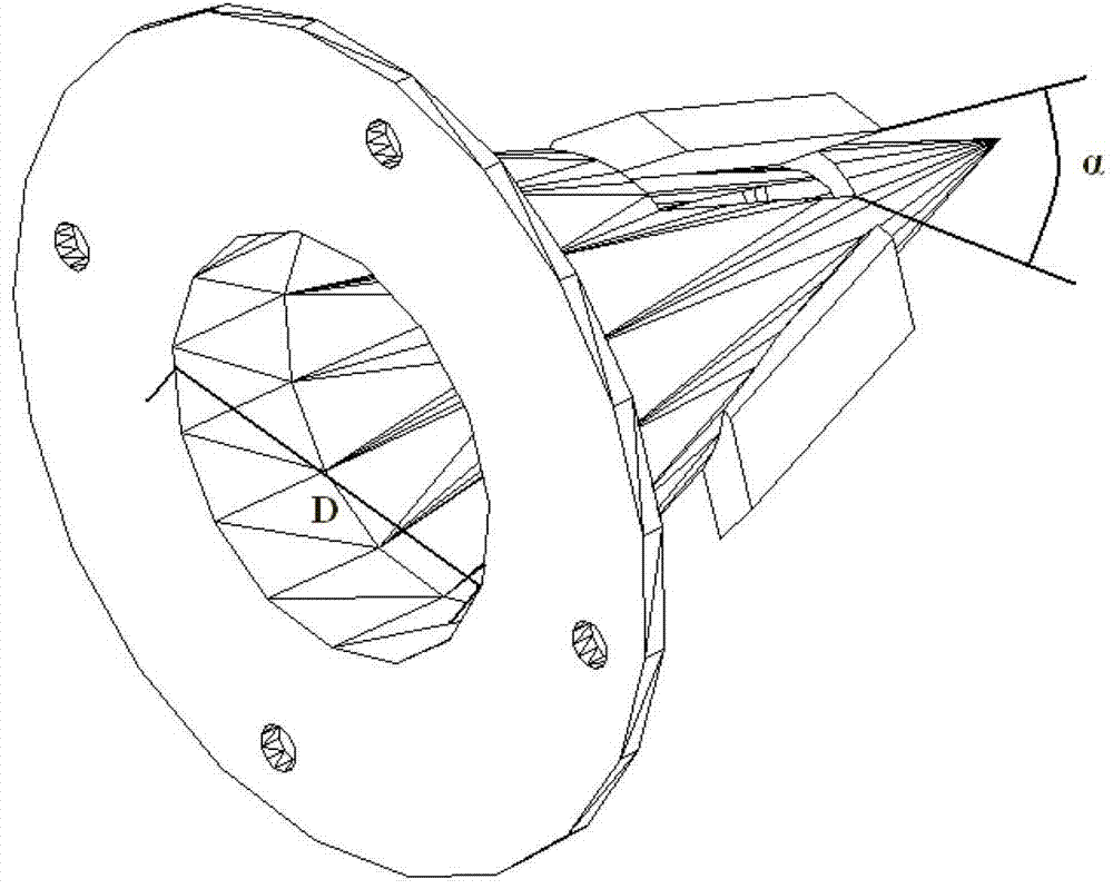
[0021] Such as figure 1 , 2 , Shown in 3, the present invention is made up of flange 10, cylinder body and fin 5 three parts. Among them, the thickness of the flange is 2 mm, and there are four evenly distributed bolt holes 9 on the surface of the flange, and the new device is firmly connected to the pipeline 1 to be connected by bolts. The barrel includes a cylindrical barrel 7 and a conical barrel 2 . Regarding the cylindrical barrel 7, the conical barrel and the flange are firmly connected by welding. The outer diameter of the barrel is the same as the inner diameter of the pipe to be connected, which is 200mm, the axial length is 50mm, and the thickness of the barrel is 2mm. Regarding the conical cylinder 2, it is one of the main components that generate the spiral flow. The inner diameter D of the bottom surface is the same as the inner diameter of the cylindrical cylinder, D=196mm, and the thickness of the conical surface of the cylinder is the same as that of the cyli...


PUM


Abstract

The invention relates to a circular cone type spiral flow generator. The circular cone type spiral flow generator comprises a flange, a tank body and a radiator-fan, wherein the flange is provided with a screw hole, the lower section of the tank body is a cylindrical tank body, the upper section of the tank body is a circular cone-shaped tank body, an inner diameter of the cylindrical tank body and an diameter of a ready-to-connect pipeline are identical, and the tail end of the cylindrical tank body is fixedly connected with the flange. An inner diameter D of the bottom surface of the cone-shaped tank body is identical to the inner diameter of the cylindrical tank body. The ratio of the height of the cone-shaped tank body and the inner diameter of the bottom surface is 1:1 to 1:2. The taper angle beta of the cone-shaped tank body satisfies the equation that beta=2arctan (D/2h). Overcurrent holes are evenly arranged along the conical surface on the surface of the circular cone-shaped tank body. The radiator-fan is arranged on the surface of the circular cone-shaped tank body and outside the overcurrent holes. The angle alpha between the bottom face of the radiator-fan and the plane of the overcurrent holes is 30 degrees to 60 degrees. According to the circular cone type spiral flow generator, a circular cone radiator-fan type rotation is adopted, the structure is novel, spiral effect is good, and spiral intensity is large. By means of the form of a setting-up piece, the entirety is easy to install. No other energy-consuming equipment needs to be added, and therefore energy consumption is low.

Description

technical field [0001] The invention relates to a fluid spiral generator, in particular to a conical spiral flow generator. Background technique [0002] Spiral flow is a flow form with a rotating flow field. It has a wide range of industrial applications, including hydraulic engineering and mechanical processing. At the same time, spiral flow technology has also entered the field of people's daily life, such as spiral flow energy-saving gas stoves. The key to the application of spiral flow lies in its generating device. At present, there are various generating methods. [0003] First, the patent "Vortex Generator" (200620068646.4, Publication (Notice) No. CN 2869720Y) provides a vortex generator, including round steel pipe, round steel and four helical blades. The four helical blades are used in the same direction of rotation. One end is evenly distributed around the round steel, the other end is arranged on the inner wall of the round steel pipe, and the axial angle betw...

Claims


Application Information

Patent Timeline
Patent Type & Authority Applications(China)
IPC IPC(8): F17D1/20
Inventor 王树立饶永超周诗岽李恩田
Owner 江苏卓燃知识产权运营有限公司
Why Eureka
Try Eureka