Medical implantable lead and method for manufacturing of such a lead

a technology of implantable lead and lead wire, which is applied in the direction of electrotherapy, contact member assembly/disassembly, transvascular endocardial electrode, etc., can solve the problems of lead disengagement from the organ, uneven winding, and complex operation, and achieves improved helix performance, low cost, and high quality

Active Publication Date: 2013-11-26
ST JUDE MEDICAL
View PDF10 Cites 1 Cited by
  • Summary
  • Abstract
  • Description
  • Claims
  • Application Information

AI Technical Summary

Benefits of technology

[0011]An object of the invention is to provide a medical implantable lead, which is possible to manufacture at a low cost, high quality and with improved helix performance.
[0013]Accordingly, the basis of the invention is the recognition that this object can be achieved by letting the inner coil extend through the entire connector pin and to attach the inner coil at the proximal end of the connector pin. In this way several advantages may be achieved. Since the inner coil is attached to the outer proximal end of the connector pin, the length of the inner coil can be cut as one of the last operations of the assembling of the medical implantable lead. Accordingly, the cut length of the inner coil can be adapted to the actual length due to the aggregate tolerances of the rest of the lead, such that the inner coil can be cut in a length that will not give any disadvantageous inherent tensions in the inner coil. As a result of this, the dimensional as well as the assembling tolerances can be allowed to increase with a lower cost for components and assembling. Also, any uneven windings of the inner coil caused by the attachment to the connector pin, will be disposed inside the inner bore of the connector pin and, accordingly, can not cause any seizing in relation to the inner tubing of the lead in case of a rotatable inner coil. Moreover, the initial length of the inner coil can be made in one size fitting all different lengths of medical implantable leads, which will reduce the number of pre-cutting fixtures. When the cutting of the inner coil is performed as one of the last operations, the possibility of getting rests of cut filaments inside the lead is reduced. It is also an advantage that the attachment of the inner coil to the connector pin will always be visible from the outside such that e.g. a weld connection can be easily verified.

Problems solved by technology

However, there are several disadvantages associated with attaching the inner coil with the connector pin in the distal end.
For one thing, this operation is complex to perform since the available space to perform the attachment is very limited.
This is due to the fact that the inner coil in practice functions as a helical spring and tensile stress will arise in the inner coil if the length is to short, since then it has to be stretched when attaching to the connector pin, with the potential risk that the helix will tend to rotate after attaching to the organ which can cause disengagement of the lead from the organ.
Moreover, when the inner coil is attached to the connector pin, this can cause the coil windings to become uneven and wave shaped, which will increase the friction against an inner tubing, which encloses the inner coil and in relation to which the inner coil is rotatable.
The aggregate dimensional tolerances of the component parts as well as the assembling tolerances will affect the actual required length of the inner coil and hence it is difficult to estimate the nominal cut length of the inner coil in advance.
This necessitates close dimensional as well as assembling tolerances, in order to limit the number of discards, and this increases the manufacturing costs for the medical implantable lead.

Method used


Image

  • Medical implantable lead and method for manufacturing of such a lead
  • Medical implantable lead and method for manufacturing of such a lead
  • Medical implantable lead and method for manufacturing of such a lead

Examples


Embodiment Construction

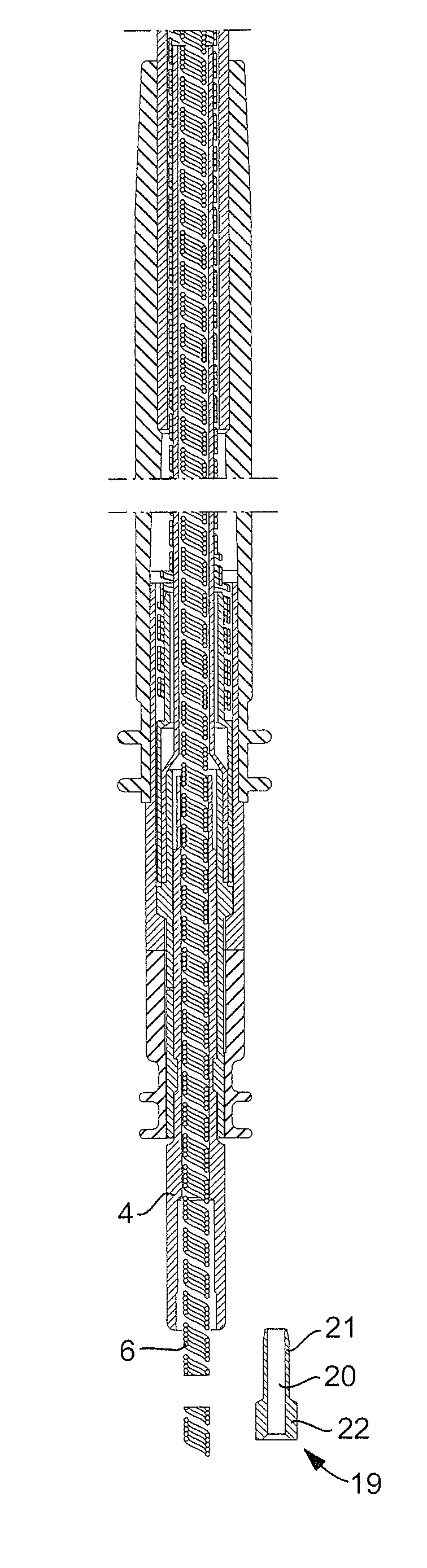
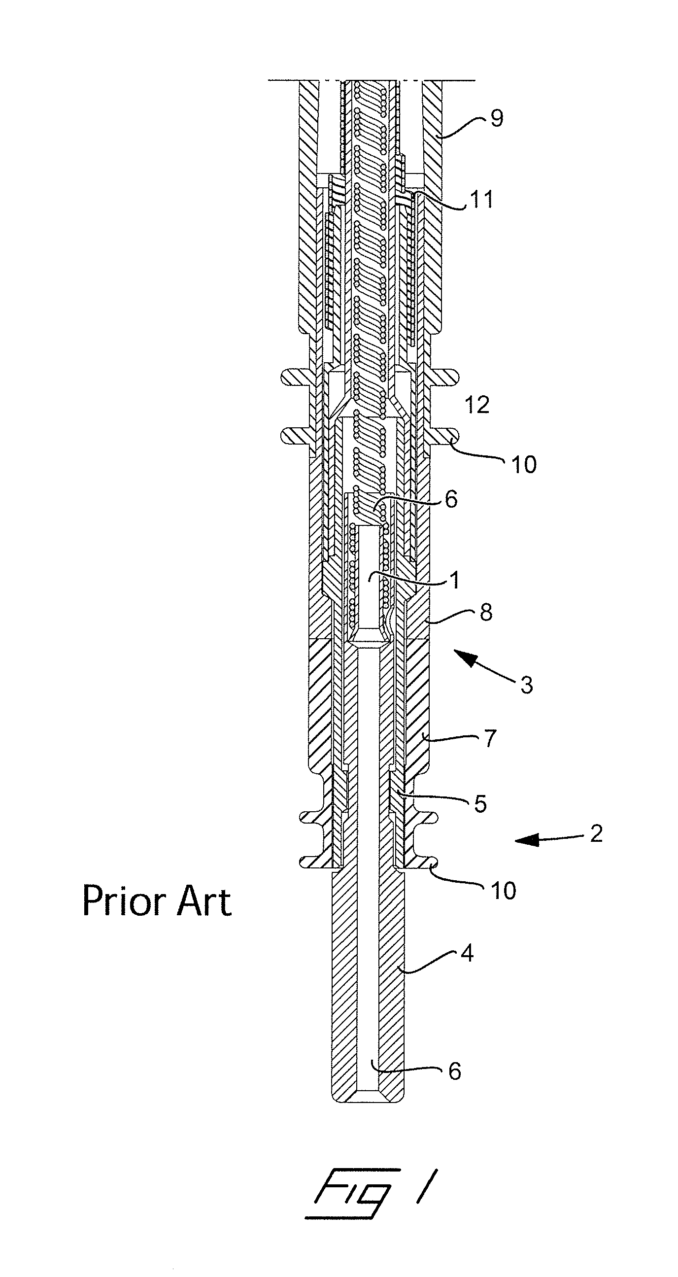
[0024]Reference is first made to FIG. 1 in which is illustrated, in a longitudinal section, a prior art embodiment of a proximal portion of a medical implantable lead. In the proximal end the lead is provided with a connector 2 for mechanical as well as electrical connection of the lead to a monitoring and / or controlling device, such as a pacemaker or a cardiac defibrillator. The connector 2 has a connector housing 3 in which a connector pin 4 is rotatably accommodated by being rotatable mounted in a bearing sleeve 5 inside the connector housing 3. The connector pin 4 is electrically conductive and is in its distal end connected, mechanically as well as electrically, to an inner coil 6 of helically wound metallic wires, e.g. by a clamp connection. More precisely, the inner coil 6 is thread onto a support tube 1, which is inserted into a bore having an enlarged diameter in the distal portion of the connector pin 4. Subsequently, the distal portion of the connector pin is deformed by ...


PUM

PropertyMeasurementUnit
lengthaaaaaaaaaa
electricalaaaaaaaaaa
mechanicalaaaaaaaaaa

Abstract

A medical implantable lead to be inserted into a human or animal body and attached to an organ inside the body for monitoring and / or controlling the function of the organ has a header in a distal end, a fixation arrangement and an electrode arranged in the header. The fixation arrangement attaches the distal end of the lead to the organ and the electrode is arranged to transmit or receive electrical signals to or from the organ. The lead also has a connector in a proximal end that includes a connector pin and is adapted to be connected to a monitoring and / or controlling device, and an inner coil, which extends inside an outer casing of the lead and is adapted to transmit electrical signals between the monitoring and / or controlling device and the electrode. The inner coil is attached to the connector pin. The inner coil extends through a bore inside the connector pin and is attached to the connector pin in its proximal end. A method for manufacturing such a lead is also provided.

Description

BACKGROUND OF THE INVENTION[0001]1. Field of the Invention[0002]The invention relates to a medical implantable lead of the type adapted to be inserted into a human or animal body and attached to an organ inside the body for monitoring and / or controlling the function of the organ, and having a header in a distal end, a fixation means and an electrode arranged in the header, wherein the fixation means attaches the distal end of the lead to the organ and the electrode is arranged to transmit or receive electrical signals to or from the organ, a connector in a proximal end that includes a connector pin and is adapted to be connected to a monitoring and / or controlling device, and an inner coil, which extends inside an outer casing of the lead and is adapted to transmit electrical signals between the monitoring and / or controlling device and the electrode, wherein the inner coil is attached to the connector pin.[0003]The invention also relates to method for manufacturing of a medical impla...

Claims


Application Information

Patent Timeline
Patent Type & Authority Patents(United States)
IPC IPC(8): A61N1/375
CPCA61N1/056Y10T29/49208
Inventor JARL, PERHILL, ROLF
Owner ST JUDE MEDICAL
Why Eureka
Try Eureka