Fuel nozzle with central body cooling system

A technology for fuel nozzles and cooling holes, which is applied in the direction of burner cooling, burner, combustion chamber, etc., and can solve the problem of damaging fuel nozzles

Inactive Publication Date: 2012-02-08
GENERAL ELECTRIC CO
View PDF5 Cites 11 Cited by
  • Summary
  • Abstract
  • Description
  • Claims
  • Application Information

AI Technical Summary

Problems solved by technology

These high temperatures can damage fuel nozzles

Method used


Image

  • Fuel nozzle with central body cooling system
  • Fuel nozzle with central body cooling system
  • Fuel nozzle with central body cooling system

Examples


Embodiment Construction

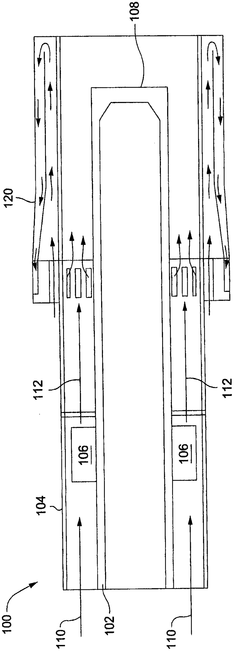
[0033] figure 1 A fuel nozzle for a turbine engine including a cooling shroud is shown. As shown, the fuel nozzle includes a generally cylindrical central nozzle area 102 located within the housing 104. The air flow indicated by arrow 110 enters the upstream end of the fuel nozzle. The air entering the fuel nozzle passes through the annular space between the outer wall of the central nozzle area 102 and the inner wall of the housing 104. The air flow passes through fuel guide vanes 106 that deliver fuel into the air flow. The fuel guide vane 106 may also be angled with respect to the longitudinal axis of the nozzle, which causes the air and fuel mixture to swirl within the fuel nozzle, and the swirl can help to mix the fuel and air.

[0034] Once the fuel is delivered to the air, the fuel-air mixture indicated by arrow 112 continues to flow in the downstream direction through the annular space between the outer side of the central nozzle area 102 and the inner wall of the housi...


PUM


Abstract

The invention relates to a fuel nozzle with a central body cooling system. Tje fuel nozzle for turbine engine includes a cooling shroud located at the downstream end of the fuel nozzle to help cool the downstream end of the fuel nozzle. The cooling shroud surrounds the exterior circumference of the downstream end of the fuel nozzle. A flow of air is admitted into the cooling shroud and the flow of air travels in the downstream direction through a first passageway which covers the exterior of the fuel nozzle. The cooling air flow then turns 180 DEG and travels in the upstream direction through a second passageway which is located concentrically outside the first passageway. The airflow then leaves the upstream end of the cooling shroud and enters the interior of the fuel nozzle.

Description

Technical field [0001] The invention relates to a fuel nozzle used in a combustor of a turbine engine. Typically, multiple fuel nozzles will be mounted on the combustor cap located at the upstream end of the combustor. The fuel nozzle delivers fuel to the compressed air stream to produce a fuel-air mixture that is subsequently burned in the combustor. Background technique [0002] Since the fuel nozzle is located just upstream of the location where the fuel-air mixture is burned, the outer surface and downstream end of the fuel nozzle are exposed to high-temperature combustion products. These high temperatures can damage the fuel nozzle. Summary of the invention [0003] In a first aspect, the present invention is embodied in a fuel nozzle for a turbine engine, the fuel nozzle including a substantially cylindrical casing and a cylindrical cooling shroud concentrically surrounding a downstream portion of the outside of the casing. The cooling shield includes a cylindrical outer ...

Claims


Application Information

Patent Timeline
Patent Type & Authority Applications(China)
IPC IPC(8): F23R3/00
CPCF23C2900/07001F23D2214/00F23R3/14F23R3/283
Inventor L·吉内辛A·瓦利夫B·谢尔什恩约夫
Owner GENERAL ELECTRIC CO
Why Eureka
Try Eureka