Link rapidly recovering method and device
A fast recovery and link technology, applied in the field of network communication, it can solve the problem that the time difference between becoming available is not easy to determine, and the fast recovery link cannot be guaranteed.
- Summary
- Abstract
- Description
- Claims
- Application Information
AI Technical Summary
Problems solved by technology
Method used
Image
Examples
Embodiment 1
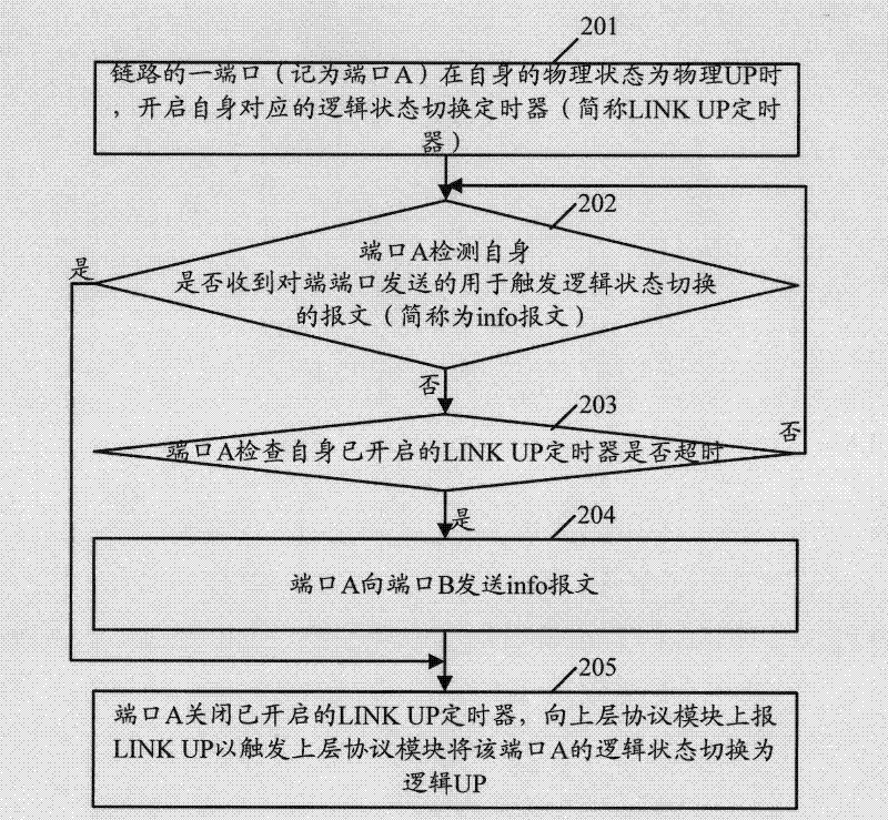
[0052] Because in the prior art, when the port of the link is physically UP, the port will immediately report to the upper-layer protocol module to trigger the upper-layer protocol module to switch the logical state of the port to logical UP, and in this embodiment 1, by controlling Among the ports at both ends of the link, the first physical UP port triggers the logical UP delay, that is, the first physical UP port waits for the second physical UP port, so that the time difference between the two ports triggering the logical UP can be shortened to achieve fast link recovery. purpose of the road. When this embodiment 1 is specifically implemented, it may include figure 2 The flow shown:
[0053] see figure 2 , figure 2 The flow chart provided for Embodiment 1 of the present invention. Such as figure 2 As shown, the process may include the following steps:
[0054] In step 201, a port of a link (referred to as port A) starts its corresponding logical state switching t...
Embodiment 2
[0090] When this embodiment 2 is specifically implemented, it may include Figure 8 The flow shown:
[0091] see Figure 8 , Figure 8 The flow chart provided for Embodiment 2 of the present invention. Such as Figure 8 As shown, the process may include the following steps:
[0092] Step 801, after a port (referred to as port A) of the link switches its physical state to physical UP, it sends a message to the opposite port (that is, the port of the opposite device connected to the link, denoted as port B). A notification message (info message for short) that triggers a logical state switching, and starts its own corresponding logical state switching timer (LINK UP timer for short).
[0093] In this embodiment, the LINK UP timer corresponding to port A may be set in port A, or may be independent of port A, which is not specifically limited in the present invention.
[0094] In step 802, port A detects whether it has received an acknowledgment message (referred to as ack m...
Embodiment 1
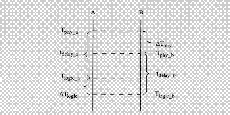
[0129] Compared with Embodiment 1, no matter what the scenario is in Embodiment 2, the logical UP time difference between the ports at both ends of the link can be shortened to no more than a message transmission time (ΔT logic tx ), therefore, this embodiment 2 has no special requirements on the cycle t started by the LINK UP timer, and is not subject to ΔT phy , ΔT tx The optimization effect is relatively stable and has a certain degree of promotion. Preferably, considering the actual situation, the processing capability of the CPU may be considered when setting t, usually not lower than 100ms.
[0130] So far, the description of the second embodiment is completed.
[0131] The method provided by the present invention has been described above, and the port module provided by the present invention is described below:
[0132] see Figure 13 , Figure 13 The device structure diagram provided for the embodiment of the present invention. The device is applied to the port i...
PUM
 Abstract
Description
Claims
Application Information
 - R&D
- Intellectual Property
- Life Sciences
- Materials
- Tech Scout
- Unparalleled Data Quality
- Higher Quality Content
- 60% Fewer Hallucinations
Browse by: Latest US Patents, China's latest patents, Technical Efficacy Thesaurus, Application Domain, Technology Topic, Popular Technical Reports.
© 2025 PatSnap. All rights reserved.Legal|Privacy policy|Modern Slavery Act Transparency Statement|Sitemap|About US| Contact US: help@patsnap.com


