Spinning assembly and spinning method thereof

A spinning component and spinning technology, applied in the field of spinning component and its spinning, can solve the problems of spinning breakage, affecting the drawing state, and breaking of filaments, so as to achieve uniform crystallization of filaments, prevent local crystallization, and prevent heat loss. loss of uniform effect

Active Publication Date: 2016-03-23
浙江恒百华化纤有限公司
View PDF5 Cites 7 Cited by
  • Summary
  • Abstract
  • Description
  • Claims
  • Application Information

AI Technical Summary

Problems solved by technology

[0004] The high polymer in the molten state in the spinning assembly, once impurities exist, spinning breakage often occurs during the stretching process, which affects the further reduction of the fiber linear density; secondly, and the most important reason, in the spinning assembly The temperature distribution of the polymer in the molten state is uneven, which causes the polymer in the polymer to crystallize in some places with lower temperature, which makes the grain distribution of the polymer in the molten state uneven, and finally leads to fiber forming. During the process, the tow breaks, so that the linear density of the fiber cannot be further reduced; finally, due to the huge difference between the external temperature of the spinning assembly and the internal temperature of the spinning assembly, the polymer in the molten state is often extruded from the spinneret When exposed to external low temperature, its crystallization state has already begun to distribute unevenly, which directly affects the subsequent crystallization process and pulling state

Method used


Image

  • Spinning assembly and spinning method thereof
  • Spinning assembly and spinning method thereof
  • Spinning assembly and spinning method thereof

Examples


Embodiment Construction

[0035] refer to Figure 1~6 The present invention will be further described.

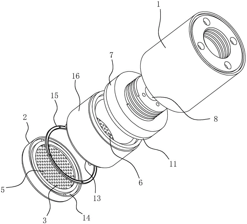
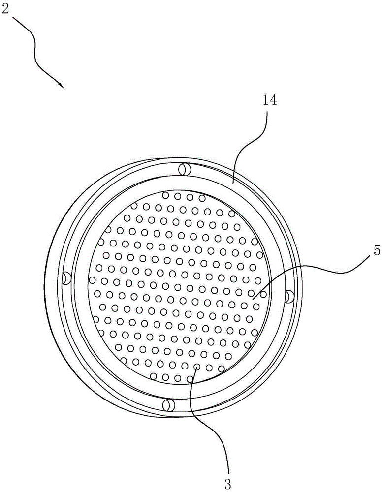
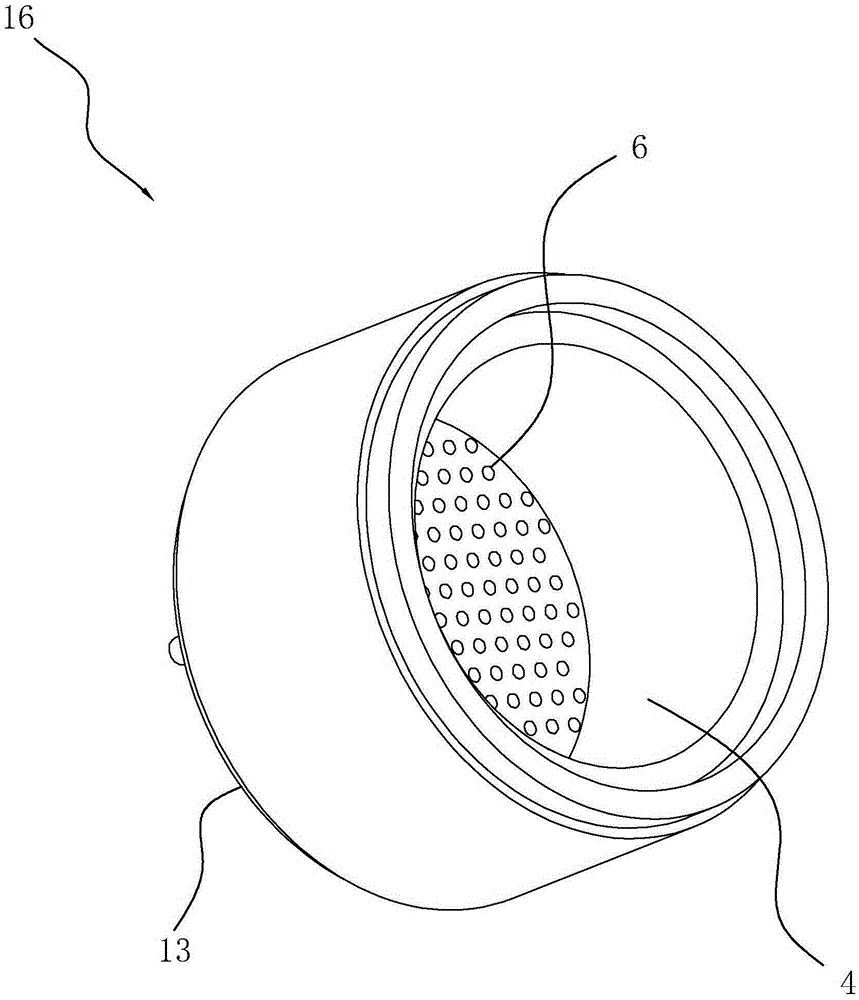
[0036] Such as Figure 1~5 As shown, a spinning assembly includes a tank 1 and a spinneret 2 arranged at the bottom of the tank 1, the spinneret 2 is provided with at least one spinneret 5 and the spinneret 5 is evenly provided with a plurality of spinnerets The holes 3 and the upper side of the spinneret 2 are sealed and connected with an accommodation chamber for accommodating the fluid. The accommodation chamber is evenly divided into at least one distribution chamber 4. The distribution chamber 4 corresponds to the spinneret area 5 one by one. There is a filter plate 6, and above the accommodating chamber, there is a flow block 7 for the fluid to enter the distribution chamber 4. The flow block 7 is provided with a main flow channel and a plurality of flow channels 8, and the fluid outlets of the flow flow blocks 8 9 corresponds to the distribution chamber 4, the horizontal section of the dist...


PUM


Abstract

The invention discloses a spinning assembly which comprises a barrel and a spinning plate. The spinning plate is provided with a spinning area which is provided with spinning holes. The upper side of the spinning plate is connected with a containing chamber, a distribution chamber is arranged in the containing chamber and corresponds to the spinning area, a filter plate is arranged in the containing chamber, a flow passing block is arranged above the containing chamber, and a main flow channel and a plurality of flow dividing channels are formed in the flow passing block. Fluid outlets of the flow dividing channels are provided with chamfers to form frustum-shaped flow dividing grooves with the fluid outlets as centers. The opening in one end, far away from a flow dividing outlet, of each flow dividing groove is as large as the opening of the distribution chamber. Flow equalizing plates are arranged between the flow dividing grooves and the distribution chamber. Each flow equalizing plate is provided with a plurality of flow passing channels from the circle center of the flow equalizing plate, and the lengths of the flow passing channels are gradually reduced. The flow equalizing plates are arranged between the fluid distribution chamber of the spinning assembly and the fluid flow dividing channels, so that time difference generated in the process that fluid enters the distribution chamber is reduced, heat loss of the fluid is more uniform, yarn bundle crystallization is more uniform, and spinning quality is improved.

Description

technical field [0001] The invention relates to the technical field of spinning, more specifically, it relates to a spinning component and a spinning method thereof. Background technique [0002] In the spinning process, it is mainly divided into melt spinning, wet spinning and dry spinning. Both dry spinning and wet spinning are made of certain polymer compounds into a colloidal solution, which is produced by the spinneret. The fine holes are pressed into the coagulation bath to coagulate or undergo chemical changes at the same time to form fibers, while the melt spinning process mainly includes the fiber-forming polymer being heated and melted in the screw extruder, and the melt is passed through the fine holes on the spinneret through the metering pump. The thin stream is formed by middle extrusion, the melt stream is cooled and solidified, and the filament is oiled and wound, and stretched and thinned to obtain a fiber. Compared with wet spinning and dry spinning, melt ...

Claims


Application Information

Patent Timeline
Patent Type & Authority Applications(China)
IPC IPC(8): D01D4/00D01D1/06
CPCD01D1/06D01D4/00
Inventor 周克含毛佳枫陈志高李永军
Owner 浙江恒百华化纤有限公司
Why Eureka
Try Eureka