A roller comprising a drive shaft and a roller ring, as well as a method for assembling such a roller
A technology for transmission shafts and rolls, applied in the direction of rolls, shafts and bearings, metal rolling, etc., can solve the problems of weakening roll structure, harmful stress, etc.
- Summary
- Abstract
- Description
- Claims
- Application Information
AI Technical Summary
Problems solved by technology
Method used
Image
Examples
Embodiment Construction
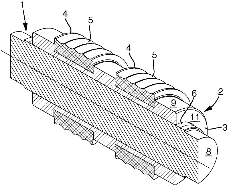
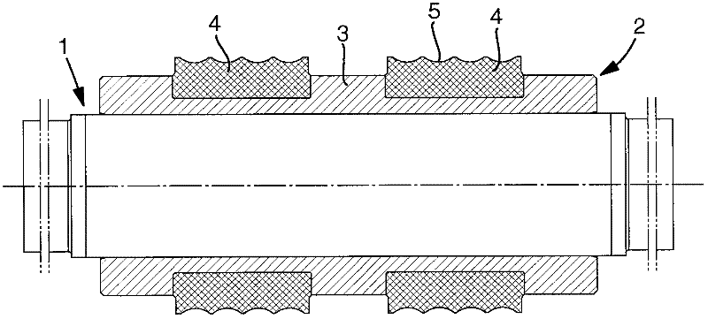
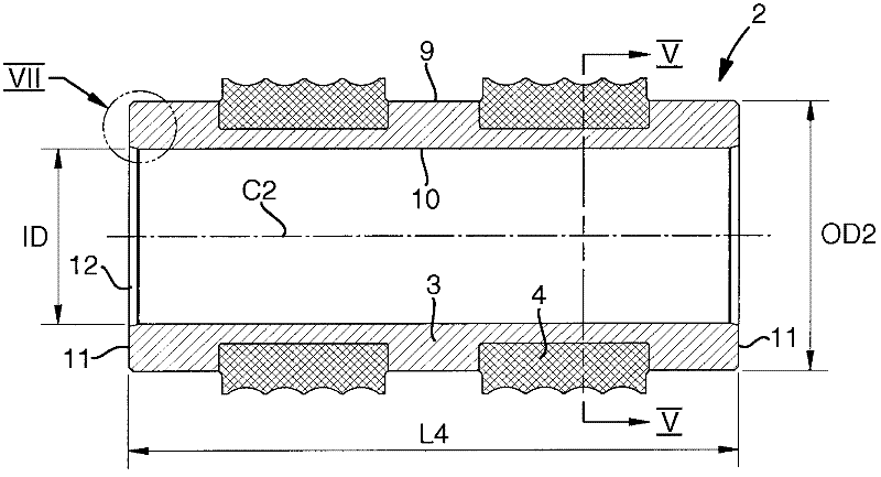
[0018] In the drawings, 1 generally denotes a roll or a drive shaft, and 2 denotes a roll ring mounted on the outside of the roll or drive shaft. In the example, said roll ring 2 comprises an inner ring 3 and two outer rings 4, in the envelope surface of which outer rings 4 are formed circumferential roll grooves 5 for rolling elongated products.
[0019] The transmission shaft 1 comprises a roller in the form of a cylindrical envelope 6 (see Figure 4 ), the roller is concentric with the central axis C1 of the shaft, and the roller transforms into an envelope surface with a journal 7 of reduced diameter at opposite ends. In this case, the ends of the shaft comprise two flat end faces 8 of journals 7 . The overall length L1 of the shaft depends on the distance between the two end faces 8 . Since each journal 7 has a certain length L2, the axial extension or length L3 of the envelope surface 6 is smaller than the overall length L1 of the shaft. The outer diameter of the shaf...
PUM
| Property | Measurement | Unit |
|---|---|---|
| diameter | aaaaa | aaaaa |
Abstract
Description
Claims
Application Information
 - R&D
- Intellectual Property
- Life Sciences
- Materials
- Tech Scout
- Unparalleled Data Quality
- Higher Quality Content
- 60% Fewer Hallucinations
Browse by: Latest US Patents, China's latest patents, Technical Efficacy Thesaurus, Application Domain, Technology Topic, Popular Technical Reports.
© 2025 PatSnap. All rights reserved.Legal|Privacy policy|Modern Slavery Act Transparency Statement|Sitemap|About US| Contact US: help@patsnap.com


