Truss sheet unit of steel truss girder, steel truss girder structure and mounting method thereof

An installation method and technology of steel truss girders, which are applied to bridges, truss bridges, bridge materials, etc., can solve problems such as the influence of bridge alignment and internal force distribution, the large number of high-strength bolt connections, and the difficulty in controlling the quality of welds, etc., to achieve reduction Splicing work, improving the quality of ex-factory products, and reducing the number of splicing times

Active Publication Date: 2012-02-15
CHINA RAILWAY MAJOR BRIDGE ENG GRP CO LTD
View PDF3 Cites 32 Cited by
  • Summary
  • Abstract
  • Description
  • Claims
  • Application Information

AI Technical Summary

Problems solved by technology

However, using this assembly method limits the speed of road and bridge construction
Specifically, the existing loose assembly method has the following disadvantages: the number of high-strength bolt connections is large, the installation speed is slow, and the installation needs to be lifted one by one. Each internode girder needs to be lifted by one upper chord during each cycle operation. 25', a lower chord 26', a web 27' and a slanting rod 28', it needs to be lifted 4 times in total, and a total of 8 times between two nodes, and each time a rod is lifted and installed, the A large number of high-strength connecting bolts need to be spliced, which cannot be operated synchronously, and the efficiency is low; the welding work of the steel truss girder erection requires a large amount of welding work, and the orthotropic plate and the main truss are connected by weld seams. Seam welding shrinkage has a great influence on bridge alignment and internal force distribution

Method used


Image

  • Truss sheet unit of steel truss girder, steel truss girder structure and mounting method thereof
  • Truss sheet unit of steel truss girder, steel truss girder structure and mounting method thereof
  • Truss sheet unit of steel truss girder, steel truss girder structure and mounting method thereof

Examples


Embodiment Construction

[0035] The invention will be further described below in conjunction with the accompanying drawings.

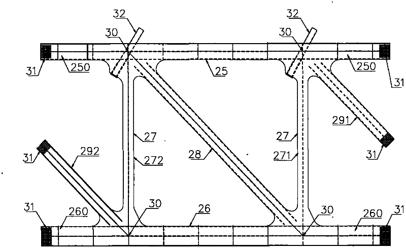
[0036] Please refer to figure 2 , figure 2 It is a structural schematic diagram of a steel truss girder unit of a steel truss structure in the present invention, and the steel truss girder unit includes an upper chord 25 and a lower chord 26 . The upper chord 25 and the lower chord 26 have the same length, and the upper chord 25 and the lower chord 26 are arranged horizontally and parallel to each other. Two vertically arranged webs 27, the two ends of the two webs 27 are welded to the upper chord 25 and the lower chord 26 to form a rectangular frame, the two ends of the upper chord 25 and the lower chord 26 are further extended to form the upper connecting rod 250 and the lower chord. connecting rod 260 . The steel truss girder truss unit is also provided with a diagonal rod 28, which connects two opposite corners of the above-mentioned rectangular frame body. The two w...


PUM


Abstract

The invention discloses a truss sheet unit of a steel truss girder, a steel truss girder structure and a mounting method thereof, relating to the design and the construction techniques of heavy-duty and large-span bridges. The steel truss girder structure consists of a plurality of the truss sheet units which are welded into a whole, wherein the truss sheet units comprise upper chord rods, low chord rods, first web rods and second web rods; the upper chord rods, the lower chord rods, the first web rods and the second web rods are welded into a rectangular frame body; two across corners of the rectangular frame body are connected by a diagonal rod; two ends of each upper chord rod further extend to form two upper connecting rods; two ends of each lower chord rod further extend to form two lower connecting rods; simultaneously, first oblique connecting rods which extend downwards are arranged among the first web rods and the upper connecting rods; and second oblique connecting rods which extend upwards are arranged among the second web rods and the lower connecting rods. When the steel truss girder is assembled, the whole truss sheet units are lifted each time; furthermore, the truss sheet units occupy two internodal lengths; the lifting times are less; the filed assembly is simple; the quantity of high-strength bolts is reduced; and the influence of the screwing of the high-strength bolts on a construction period is decreased.

Description

technical field [0001] The invention relates to the design and construction technology of heavy-load and long-span bridges, in particular to a steel truss girder truss unit, a steel truss girder structure and an installation method thereof. Background technique [0002] The steel truss is generally composed of two girders or three girders, of which the two girders include two side girders, and the three girders include two side girders and one middle girder. Between the upper chord of the middle truss and the upper chord of the side truss, there is a road orthotropic plate that constitutes the highway bridge deck. The road orthotropic plate is respectively connected with the upper chord of the middle truss The upper chord of the truss, the upper chord of the side girder, the first web, the second web and the lower surface of the road orthotropic plate are connected. The railway orthotropic plate constituting the railway bridge deck is arranged between the middle truss botto...

Claims


Application Information

Patent Timeline
Patent Type & Authority Applications(China)
IPC IPC(8): E01D21/00E01D21/10E01D6/00E01D101/30
Inventor 李军堂秦顺全涂满明毛伟琦王东辉傅战工许颖强许佳平汪芳进张维胡军
Owner CHINA RAILWAY MAJOR BRIDGE ENG GRP CO LTD
Why Eureka
Try Eureka