

Power tool
A technology of electric tools and voltage, applied in manufacturing tools, single motor speed/torque control, portable motorized devices, etc., can solve problems such as deterioration of working ability and inability to control the number of revolutions, and achieve the effect of precise control
- Summary
- Abstract
- Description
- Claims
- Application Information
AI Technical Summary
Problems solved by technology
Method used
Image

Examples
Embodiment 1
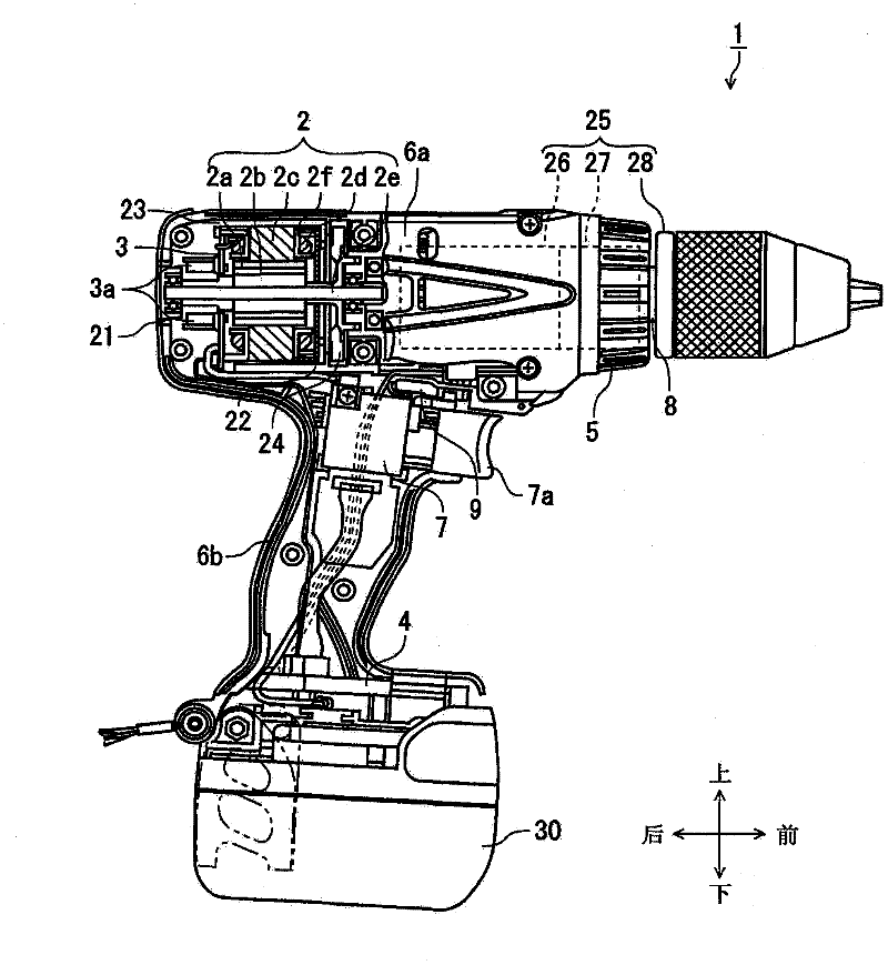
[0039] Now, the embodiments will be described in detail with reference to the accompanying drawings. In this specification, the upper, lower, front and rear directions respectively correspond to such as figure 1 these directions shown. figure 1A power tool according to an embodiment is shown, a portion of which is shown in cross-section. Although the driver drill 1 is used as an example for description in this embodiment, the present invention is not limited to this, and it can also be applied to other electric tools such as impact drivers and hammer drills.
[0040] exist figure 1 , the driver drill 1 includes a motor 2 in a cylindrical housing part 6a, and the driver drill 1 rotates a tip tool (not shown) through a power transmission part 25 for transmitting the driving power of the motor 2, for example, detachable The driver and bit are attached to the chuck 28 mounted on the mandrel (output shaft) 8 . An inverter circuit portion (circuit board 3) for driving the mot...
Embodiment 2
[0069] refer to Figure 9 and Figure 10 , the flow of control processing of the motor in the second embodiment will be described. In the first embodiment, every time the switch trigger 7 is pushed, the target number of revolutions based on the power supply voltage is set. On the other hand, in the second embodiment, the target speed is reset by detecting the battery voltage when the rotation number mode selection switch 42 is switched, without performing frequent changes of the target rotation number. Figure 9 Control status is shown. exist Figure 9 , the Y-axis represents the power supply voltage (voltage of the battery pack 30 ) and the target number of revolutions (rpm) of the motor 2 , and the X-axis represents time (sec). exist Figure 9 In the lower part of , the operation state of the switch flip-flop 7 (the output of the switch operation detection circuit 40 ) and the output signal of the speed mode selection switch 42 are also shown accordingly.
[0070] exis...
Embodiment 3
[0075] Next, refer to Figure 11 to Figure 13 , the third embodiment will be described. Figure 11 The relationship between the target number of revolutions of the motor and the output torque is shown. In the comparative example method for controlling the number of revolutions of the motor with a fixed PWM duty cycle, when the current flowing through the motor increases due to an increase in load such as repulsive force from the tip tool, the number of revolutions of the motor is proportional to the current. decreases inversely proportional, as indicated by the dashed line 111 . On the other hand, in the constant speed control method employing the PID control as represented by the solid line 113, in order to make the motor rotate at the target speed, the deviation between the output and the target value, and the integration and differentiation thereof are used by feedback. of the three items to perform control of the input value. By using PID control in this way, the number o...
PUM
 Abstract
Description
Claims
Application Information