
Core pulling mechanism of Audi car door cover plate injection mold

A technology of injection mold and core-pulling mechanism, applied in the field of core-pulling mechanism, can solve the problems of easy failure, high cost, low injection molding production efficiency, etc., and achieve the effect of simplifying the mechanism, reducing the volume and improving the efficiency

Active Publication Date: 2012-02-22
宁波宇升模塑有限公司
View PDF4 Cites 16 Cited by
  • Summary
  • Abstract
  • Description
  • Claims
  • Application Information

AI Technical Summary

Problems solved by technology

[0002] Injection molding Audi car door cover products requires horizontal demoulding and core pulling on the outer surface and outer surface of the product. Since the molding of the outer surface of the injection molded product involves the cavity of the injection mold, the injection mold usually sets the cavity in the mold. The fixed mold part, also known as the fixed mold cavity, is set in this way to facilitate the final ejection and demoulding of the product from the movable mold core. Many difficulties have been solved. The existing technology uses multiple oil cylinders to perform joint core-pulling on the fixed mold. The joint core-pulling of multiple oil-cylinders leads to complex mold mechanism, large volume and high cost. In addition, the joint core-pulling of multiple oil-cylinders makes the sequence logic The relationship is complex, prone to failure, and the injection molding production efficiency is low. Therefore, the existing technology has the problems and deficiencies of complex mechanism, large volume, high cost, many failures, and low efficiency.

Method used


Image

  • Core pulling mechanism of Audi car door cover plate injection mold
  • Core pulling mechanism of Audi car door cover plate injection mold
  • Core pulling mechanism of Audi car door cover plate injection mold

Examples


Embodiment Construction

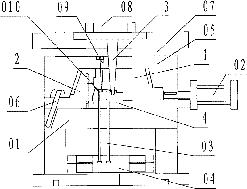
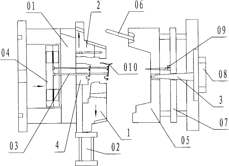
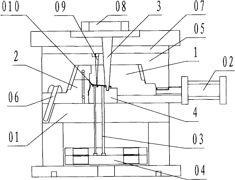
[0021] refer to figure 1 , a core-pulling mechanism for an Audi car door cover injection mold of the present invention, comprising a first cavity slider 1, a second cavity slider 2, a top hole core slider 3, a movable mold core 4, a fixed mold 05, wherein: the first cavity slider 1 is a steel horizontal core-pulling slider with slide rails slidingly connected to the movable mold 01; the first cavity slider 1 is arranged on the movable mold core On the right side of 4, the left upper part of the first cavity slider 1 is covered above the top profile of the dynamic model core 4, and the first cavity slider 1 is provided with a molded product corresponding to the position of the top profile of the dynamic model core 4 The cavity on the outer surface of 010 that requires horizontal core pulling is called the first cavity; the right side of the first cavity slider 1 is connected to the piston rod of the cylinder 02 fixed on the movable mold 01, and the first cavity slider 1 Driven...


PUM


Abstract

The present invention discloses a core pulling mechanism of an Audi car door cover plate injection mold. The core pulling mechanism comprises a first cavity slider (1), a second cavity slider (2), a top hole core slider (3), a moving mold core (4) and a fixed mold (05). The core pulling mechanism of the present invention adopts the following technical scheme that: the cavities are arranged on thefirst cavity slider and the second cavity slider, wherein the cavities provide the outer shaped surface for the shaped product, and the outer shaped surface of the shaped product requires the transverse core pulling; the first cavity slider and the second cavity slider are arranged on the moving mold; the top hole core slider of the top hole of the shaped product is arranged on the fixed mold; with mold opening and oblique guide pillar driving, the top hole core slider is longitudinally pulled while the second cavity slider is transversely pulled, then the first cavity slider is transversely pulled with the oil cylinder; finally the product is ejected from the moving mold core by an ejection rod. With the technical scheme of the present invention, the problems and the defects of complex mechanism, large volume, high cost, more failures and low efficiency are overcome, the purposes of mechanism simplifying, volume reducing, cost reducing, reliable operation and efficiency improving of the Audi car door cover plate injection mold are achieved.

Description

technical field [0001] The invention relates to an injection mold, in particular to a core-pulling mold for an Audi car door cover plate which is used for injection molding Audi car door cover plate products, and can perform horizontal core-pulling and demoulding on the outer surface and outer surface of the product. mechanism. Background technique [0002] Injection molding Audi car door cover products requires horizontal demoulding and core pulling on the outer surface and outer surface of the product. Since the molding of the outer surface of the injection molded product involves the cavity of the injection mold, the injection mold usually sets the cavity in the mold. The fixed mold part, also known as the fixed mold cavity, is set in this way to facilitate the final ejection and demoulding of the product from the movable mold core. Many difficulties have been solved. The existing technology uses multiple oil cylinders to perform joint core-pulling on the fixed mold. The...

Claims


Application Information

Patent Timeline
Patent Type & Authority Applications(China)
IPC IPC(8): B29C45/33B29C45/40
Inventor 叶元建顾宏科
Owner 宁波宇升模塑有限公司
Learn More