Touch sensing device and method of touch panel

A technology of touch panel and touch sensing, applied in the input/output process of data processing, input/output of user/computer interaction, instruments, etc., which can solve the problem of slow touch response time and high channel number touch signals Solve the problems of circuit and pixel light transmittance drop, and achieve the effect of fast touch response time, high sensing resolution, and less peripheral wiring

Active Publication Date: 2014-04-16
AU OPTRONICS CORP
View PDF3 Cites 0 Cited by
  • Summary
  • Abstract
  • Description
  • Claims
  • Application Information

AI Technical Summary

Problems solved by technology

If the manufacturer is unwilling to sacrifice the sensing resolution of the touch screen, the touch signal processing circuit 230 with a higher number of channels and more expensive has to be used, resulting in an increase in cost
In addition, because each sensing unit 270 needs to be coupled to the touch signal processing circuit 230 through the touch signal reading line 280, as the distribution density of the sensing units 270 increases, the peripheral wiring of the touch panel 220 also needs to be connected to the touch signal processing circuit 230. will increase accordingly, resulting in the width of the frame (not shown) of the touch panel 220 must also increase
[0008] Although this active touch sensing device can perform multi-touch sensing, since the sensing unit 270 of this structure is composed of thin film transistors, the aperture ratio of the pixel is reduced. ratio) leading to a decrease in the light transmittance of the pixel
In addition, because the sensing unit 270 of this structure is coupled to the gate line 250 and must operate with the scanning speed of the gate line 250, the touch response time of this touch screen is relatively slow.

Method used


Image

  • Touch sensing device and method of touch panel
  • Touch sensing device and method of touch panel
  • Touch sensing device and method of touch panel

Examples


no. 1 example

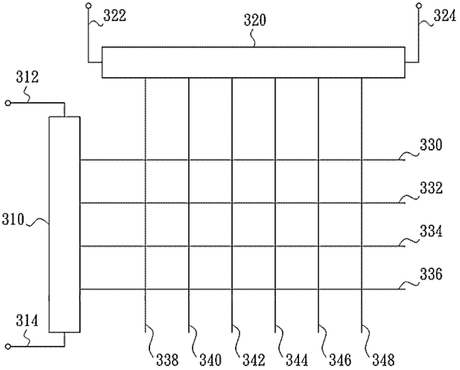
[0062] Please refer to image 3 , which shows a touch sensing device for a touch panel according to an embodiment of the present invention, which is suitable for sensing two-dimensional coordinates of a touch position. As shown in the figure, the touch sensing device mainly includes a conductor 310 , a conductor 320 and wires 330 - 348 . In addition, the touch sensing device also includes touch signal readout lines 312 , 314 , 322 and 324 . The wires 330 - 336 are arranged in parallel, and one end of the wires 330 - 336 is electrically coupled to the conductor 310 to divide the conductor 310 into a plurality of line segments. The wires 338 - 348 are arranged in parallel, and one end of the wires 338 - 348 is electrically coupled to the conductor 320 to divide the conductor 320 into a plurality of line segments.

[0063] The conductors 310 and 320 are made of special materials, so that the resistance of each line segment in the conductors 310 and 320 is greater than the resis...

no. 2 example

[0080] It can be seen from the teaching of the first embodiment that if only image 3 The conductor 310 and the wires 330 - 336 of the touch sensing device shown, or only the conductor 320 and the wires 338 - 348 can be used to sense the touch position. If only the one-dimensional coordinate sensing of the touch position is implemented, it is only necessary to measure two resistance values ​​from the two ends of the conductor, and calculate the one-dimensional coordinate of the touch position accordingly; however, if the touch position is to be implemented For the sensing of the two-dimensional coordinates of the touch position, it is necessary to cooperate with the above formulas (1)-(2) or formulas (3)-(4) to further calculate the coordinates of another dimension.

no. 3 example

[0082] This embodiment is one of the implementation states of the first embodiment. Please refer to Figure 8 , which shows a touch sensing device for a touch panel according to another embodiment of the present invention. exist Figure 8 Among them, marks 810 and 820 all represent conductors, marks 812, 814, 822 and 824 all represent touch signal reading lines, and marks 830-856 all represent wires. In this embodiment, the line width of the wires 830-856 is increased to reduce the resistance of the wires 830-856.


PUM


Abstract

The invention provides a touch sensing device and method of a touch panel. The touch sensing device comprises a plurality of parallel-arranged first leads and a first conductor, one end of each first lead is electrically coupled with the first conductor so that the first conductor is divided into a plurality of first segments, the resistance value of each first lead is less than that each segment, wherein when an external force is applied to a display region of the touch panel, the first lead corresponding to the position pointed by the external force is electrically coupled with a reference potential. The touch sensing device provided by the invention has the capability of sensing multipoint touch; and according to the touch sensing device provided by the invention, the aperture opening ratio of the pixels can not be reduced and the touch response speed is higher because no any transistor is used for forming a sensing unit.

Description

[0001] This application is a divisional application of the patent application with the application number 200910176035X, the filing date is September 22, 2009, and the invention title is "Touch Sensing Structure and Touch Sensing Method for Touch Panel". technical field [0002] The present invention relates to touch panel technology, and in particular to a touch sensing device for a touch panel and a touch sensing method thereof. Background technique [0003] With the vigorous development of touch screens, two types of touch sensing devices with built-in touch screens have been widely used, one of which is a passive touch sensing device, and the other is a passive touch sensing device. It is an active touch sensing device, respectively as figure 1 and figure 2 shown. [0004] figure 1 That is a schematic diagram of a touch screen using a passive touch sensing device. Please refer to figure 1 , the touch screen includes a data driver 110 , a touch panel 120 and a touch...

Claims


Application Information

Patent Timeline
Patent Type & Authority Patents(China)
IPC IPC(8): G06F3/03G06F3/045
Inventor 黄功杰黄宏基李锡烈
Owner AU OPTRONICS CORP
Why Eureka
Try Eureka