Sinew-tensioning bench
A technique of Lajin stool and stool surface, applied in the field of Lajin stool, can solve problems such as inconvenience, and achieve the effects of comfort, ease of use and enhanced effect.
- Summary
- Abstract
- Description
- Claims
- Application Information
AI Technical Summary
Problems solved by technology
Method used
Image

Examples
Embodiment Construction
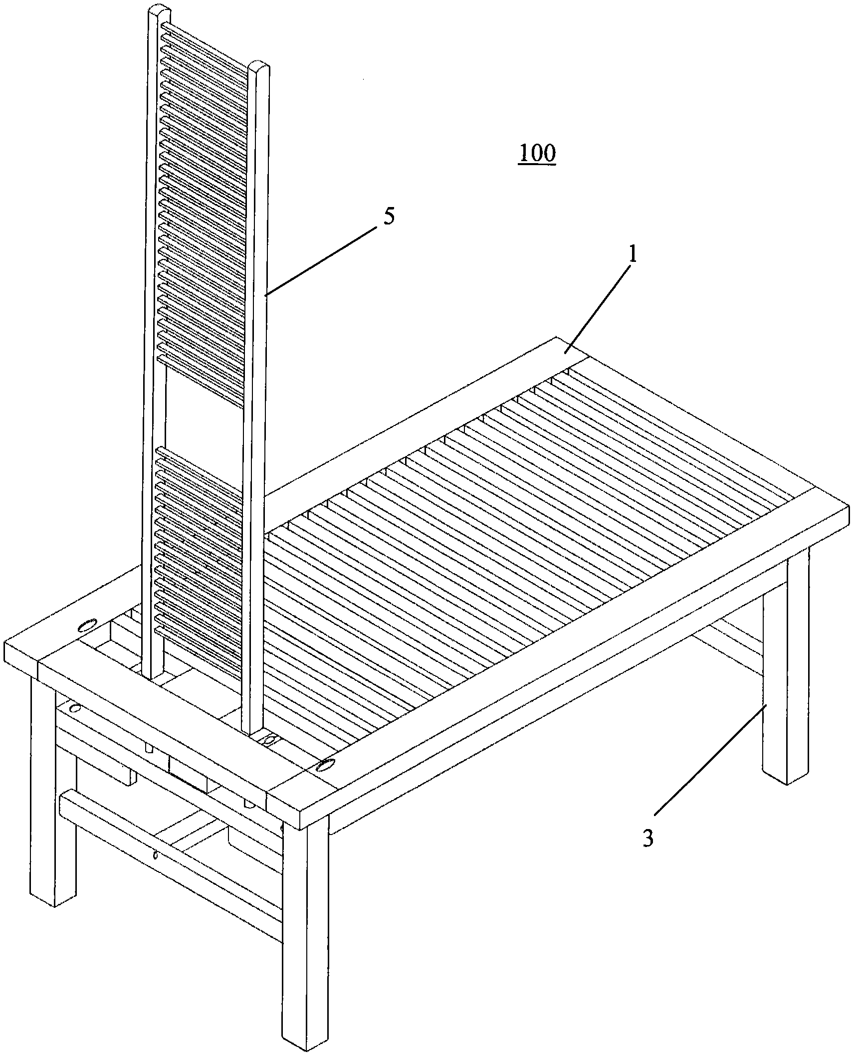
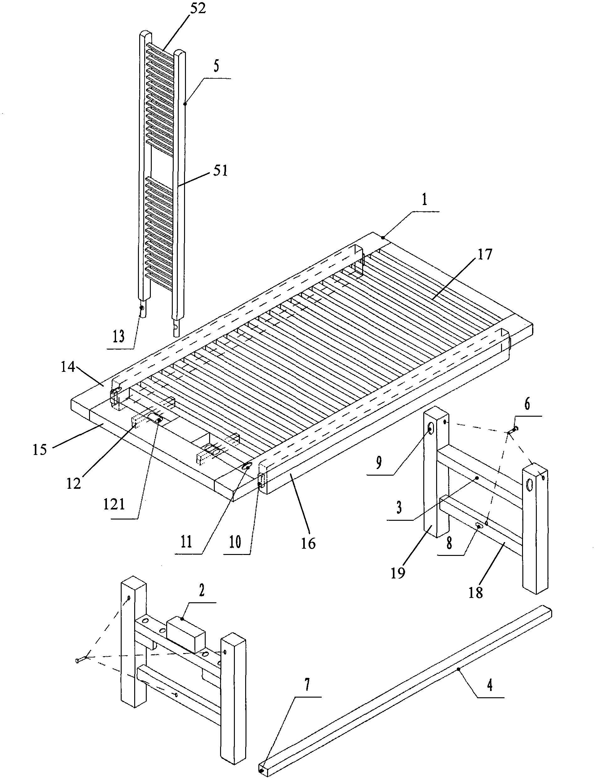
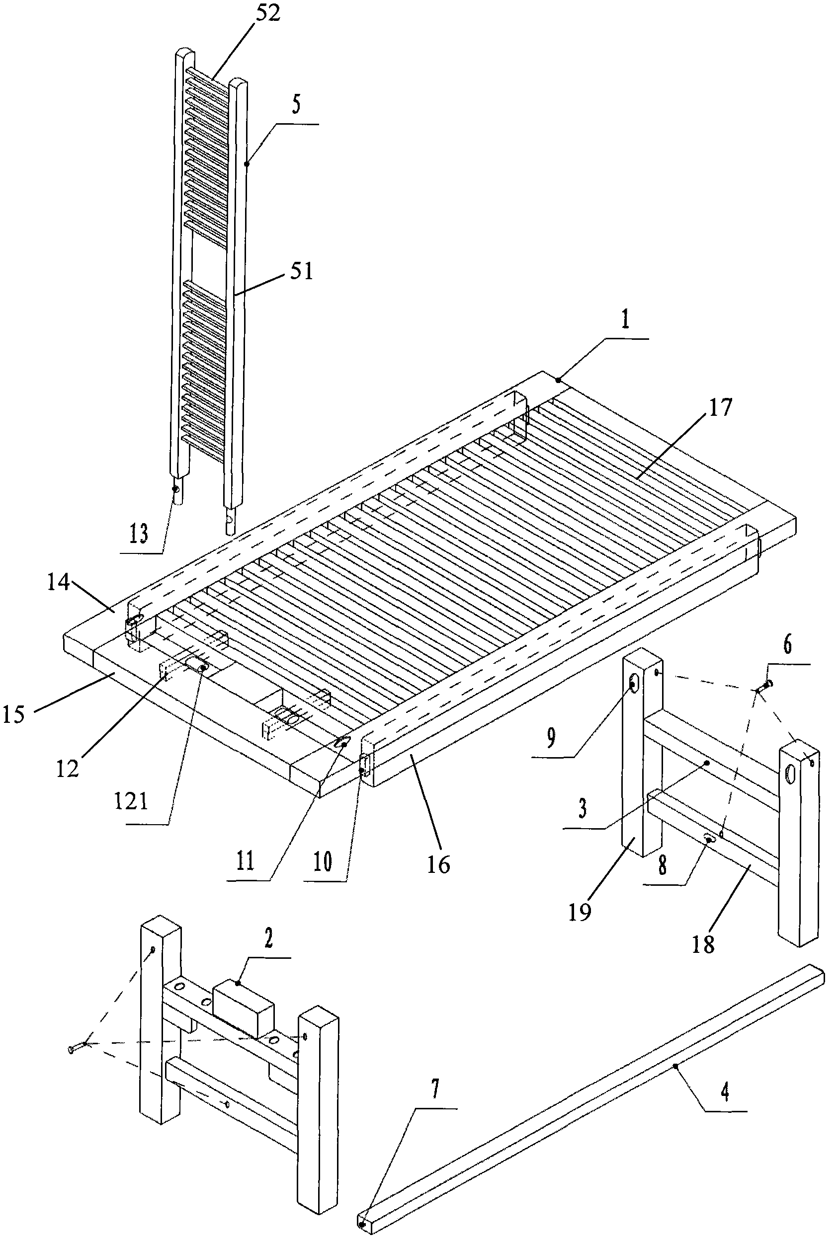
[0014] see figure 1 , figure 2 As shown, it is an exploded perspective view and an assembled perspective view of a preferred embodiment of the Lajin stool provided by the present invention. The Lajin stool 100 includes a rectangular stool surface 1 and stool frames 3 respectively located under the two ends of the stool surface 1. , the support portion 2 positioned on the stool frame 3, the beam 4 connecting the two stool frames 3, the vertical rod 5 positioned above the stool surface 1 and close to one end of the support portion 2, and some fixing screws 6.
[0015] see figure 2 As shown, the rectangular stool surface 1 includes two long frames 14 and two short frames 15 surrounding each other, two longitudinal positioning beams 16 located on the bottom surface of the long frames 14, and two longitudinal positioning beams 16 located between the positioning beams 16. A plurality of grids 17 arranged in parallel, and a sliding rod 12 located between the positioning beams 16 ...
PUM
 Abstract
Description
Claims
Application Information
 - R&D
- Intellectual Property
- Life Sciences
- Materials
- Tech Scout
- Unparalleled Data Quality
- Higher Quality Content
- 60% Fewer Hallucinations
Browse by: Latest US Patents, China's latest patents, Technical Efficacy Thesaurus, Application Domain, Technology Topic, Popular Technical Reports.
© 2025 PatSnap. All rights reserved.Legal|Privacy policy|Modern Slavery Act Transparency Statement|Sitemap|About US| Contact US: help@patsnap.com