Eureka AIR delivers breakthrough ideas for toughest innovation challenges, trusted by R&D personnel around the world.

Elevator control device

An elevator control device and elevator technology, which is applied to circuits, electrical components, secondary batteries, etc., can solve problems such as increasing the rated current value of power switching components, system faults, and the influence of energy flow paths, so as to achieve elevator energy saving, reduce The effect of electrical capacity and power consumption optimization

Active Publication Date: 2014-08-13
SHANGHAI MITSUBISHI ELEVATOR CO LTD
View PDF16 Cites 0 Cited by
  • Summary
  • Abstract
  • Description
  • Claims
  • Application Information

AI Technical Summary

Problems solved by technology

[0005] (1) Since the voltage level of the energy storage device is usually much lower than the DC bus voltage of the elevator, when the elevator motor generates regenerative energy with a certain power and needs to be stored in the energy storage device, the energy storage device in the charging and discharging circuit is often A large current is generated on the side, which will greatly increase the rated current value of the power switching elements that make up the charging and discharging circuit, which will lead to a significant increase in cost
[0006] (2) The control of the charging and discharging circuit of this structure is difficult
In this way, when any component that constitutes the energy flow path is abnormal, the energy flow path will be seriously affected or even completely interrupted, which will inevitably lead to the failure of the energy flow to be completed smoothly, resulting in a serious failure of the system
Therefore, the reliability of the charging and discharging circuit of this structure is very low, and it is difficult to meet the high reliability requirements of the elevator

Method used


Image

  • Elevator control device
  • Elevator control device
  • Elevator control device

Examples


Embodiment Construction

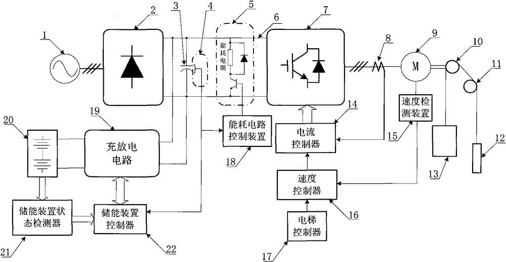
[0045] see figure 1, in this embodiment, the external power supply 1 is connected to the three-phase AC side of the rectifier 2, and the 2-phase DC side of the rectifier 2 is connected to the 2-phase DC side of the inverter 7 via the DC bus 6, and the smoothing DC capacitor 3 and energy consumption The circuit 5 is respectively connected across the two ends of the DC bus 6, the bus voltage detection device 4 is arranged at both ends of the smoothing DC capacitor 3, the 3-phase AC side of the inverter 7 is connected to the elevator motor 9 through the current detection device 8, and the elevator motor 9 is connected with the traction sheave 10 through a specific structure, and the car 13 and the counterweight 12 are suspended on both sides of the traction sheave 10 and the guide sheave 11 through ropes. The elevator controller 17 generates the speed command value for elevator operation according to the landing call, the car command or the deployment command of the group control...


PUM


Abstract

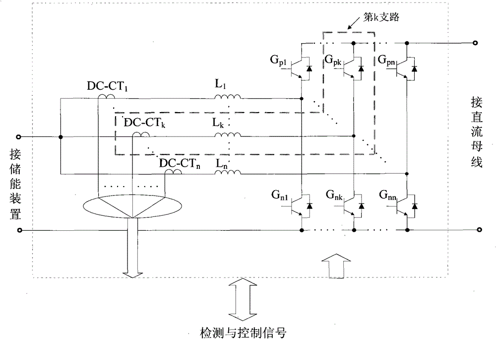
The invention discloses an elevator control device which comprises an energy storage device (20), a bus voltage detection device (4), an energy storage device state detector (21), a charge / discharge circuit (19) and an energy storage device controller (22), wherein the charge / discharge circuit comprises n (n>=2) parallel branches; and the energy storage device controller (22) can determine and distribute and control the regenerated energy or power needing to be transferred between the DC (direct current) bus and the energy storage device (20) among the branches of the charge / discharge circuit (19) so as to realize energy or power transfer between the energy storage device (20) and the DC bus. According to the invention, the functions of 'regeneration energy storage and electric energy releasing' of the conventional energy storing elevator energy saving device as well as the functions of system fault tolerance, effective reduction of electric parameter and power consumption of power module, the prolonging of service life and the like can be realized, and the equipment capacity of the elevator power system can be effectively reduced.

Description

technical field [0001] The invention relates to an elevator control device, in particular to an elevator control device which utilizes a charging and discharging circuit containing n branches and an energy storage device to realize energy saving of the elevator and reduce the electric capacity of the elevator power supply equipment. Background technique [0002] The elevator motor is in a regenerative state when it is light-loaded up and heavy-loaded down, and it will generate regenerative energy and send it back to the DC bus. For the regenerative energy on the DC bus, the energy consumption resistance method is to use the energy consumption resistance to convert the regenerative energy into heat and release it to solve the processing problem of the regenerative energy. However, this method simply converts the regenerative energy into heat energy and releases it, which objectively causes a lot of energy waste; the energy feedback method uses a PWM rectifier to return the re...

Claims


Application Information

Patent Timeline
Patent Type & Authority Patents(China)
IPC IPC(8): B66B1/00B66B5/00H01M10/46
CPCY02E60/10
Inventor 陈玉东
Owner SHANGHAI MITSUBISHI ELEVATOR CO LTD
Why Eureka
Eureka Blog
Learn More