Indoor unit of air-conditioning apparatus and air-conditioning apparatus

A technology for air conditioners and indoor units, applied in the field of indoor units, can solve problems such as inability to deliver airflow

Active Publication Date: 2012-03-14
MITSUBISHI ELECTRIC CORP
View PDF6 Cites 25 Cited by
  • Summary
  • Abstract
  • Description
  • Claims
  • Application Information

AI Technical Summary

Problems solved by technology

Therefore, there is a problem that airflows of different air volumes cannot be delivered to different places in the room.

Method used


Image

  • Indoor unit of air-conditioning apparatus and air-conditioning apparatus
  • Indoor unit of air-conditioning apparatus and air-conditioning apparatus
  • Indoor unit of air-conditioning apparatus and air-conditioning apparatus

Examples


Embodiment approach 1

[0034]

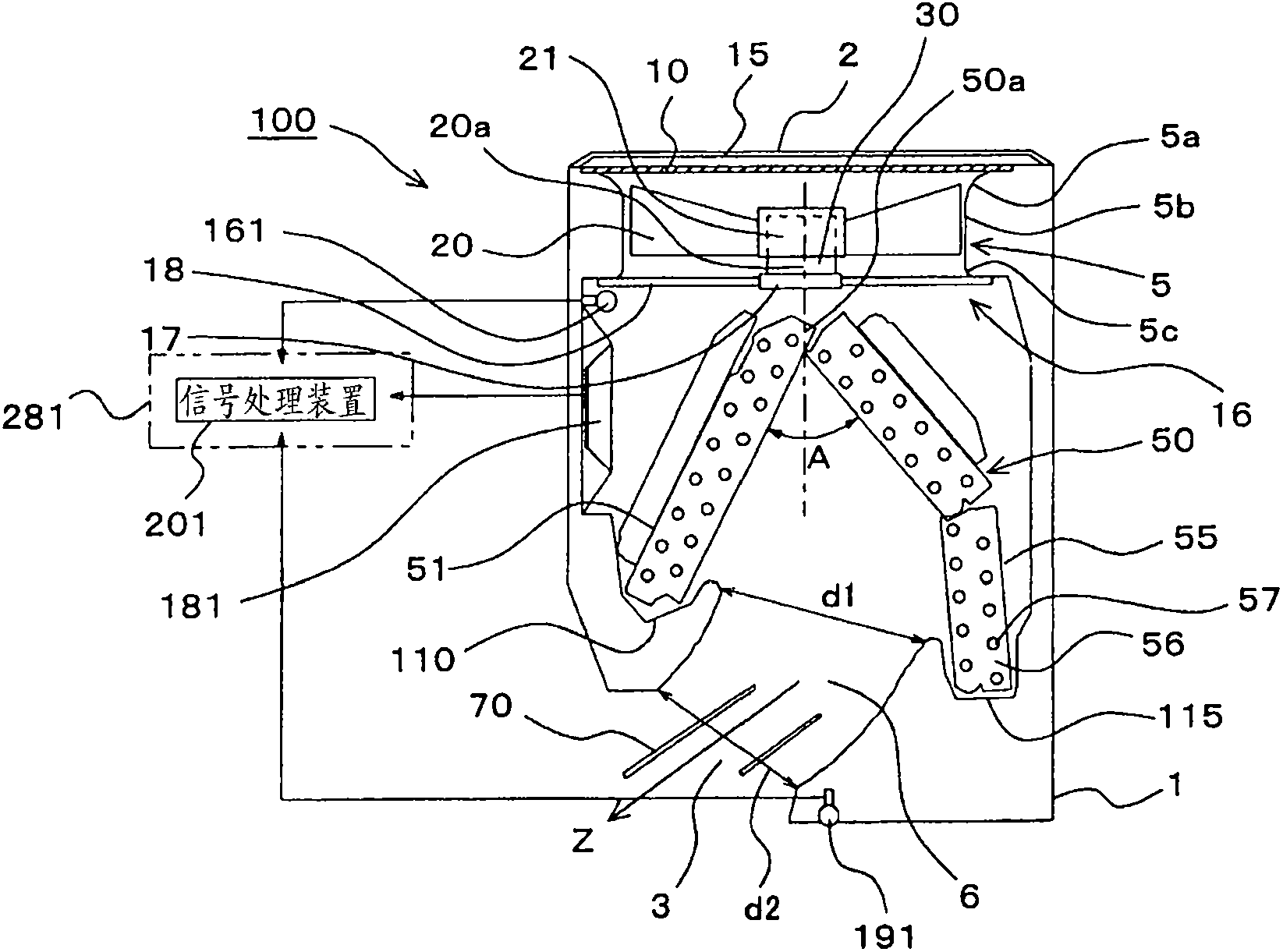
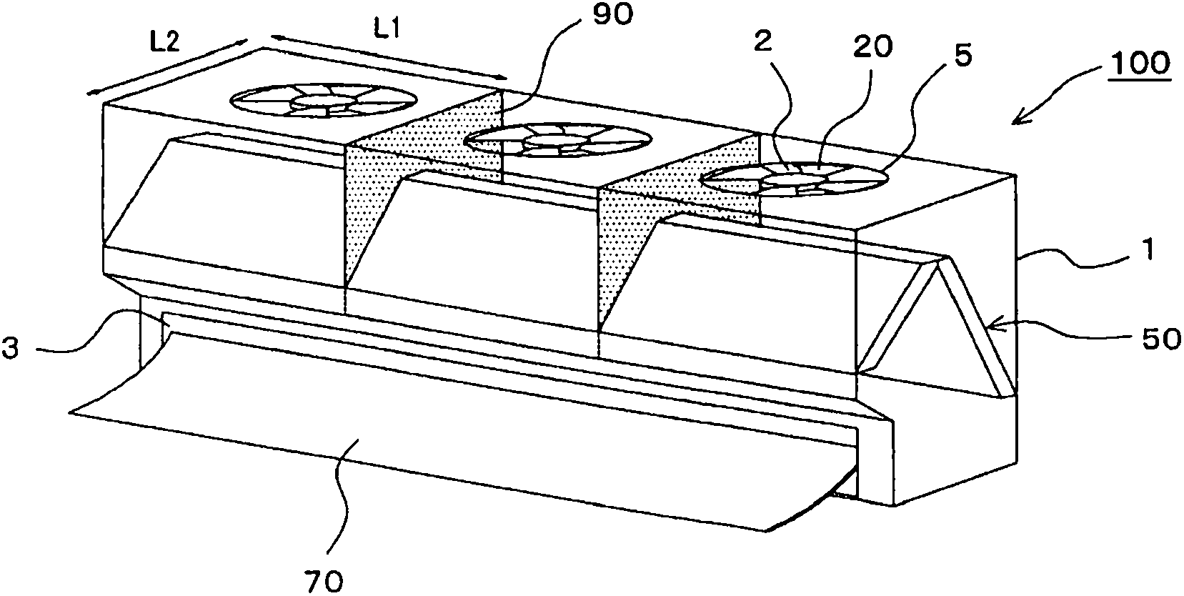
[0035] figure 1 It is a longitudinal sectional view showing the indoor unit (referred to as the indoor unit 100 ) of the air conditioner according to Embodiment 1 of the present invention. figure 2 is a perspective view showing the appearance of the indoor unit. In Embodiment 1 and the embodiments described later, the figure 1 The left side of the indoor unit 100 will be described as the front side. The following is based on figure 1 with figure 2 Next, the structure of the indoor unit 100 will be described.

[0036] (overall structure)

[0037] The indoor unit 100 supplies conditioned air to an air-conditioned area such as a room by utilizing a refrigerating cycle that circulates a refrigerant. The indoor unit 100 mainly includes a casing 1 , a fan 20 and a heat exchanger 50 . The casing 1 is formed with a suction port 2 for sucking indoor air into the interior and a blower port 3 for supplying air-conditioning air to an air-conditioning target area. The ...

Embodiment approach 2

[0131] (split leaves into multiples)

[0132] When controlling the air volumes of the upper and lower blades 70, the left and right blades 80, and the respective fans 20 based on the detection results of the infrared sensor 410, the upper and lower blades 70 and the left and right blades 80 can be divided into a plurality, and these blades can be controlled separately. In this way, comfort can be further improved. In addition, in this second embodiment, items not particularly described are the same as those in the first embodiment, and the same functions and structures are described using the same symbols.

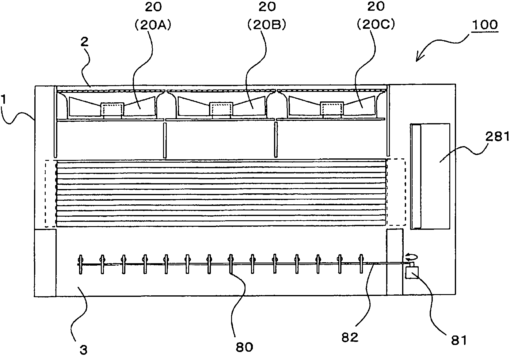
[0133] Figure 11 It is a front sectional view showing the indoor unit according to Embodiment 2 of the present invention. Figure 12 is a perspective view showing the indoor unit. in addition, Figure 11 It is a front cross-sectional view cut along the approximate center of the fan 20 .

[0134] In the indoor unit 100 according to Embodiment 2, the vertical vanes 70 ...

Embodiment approach 3

[0142] (Divide the blades into the same number as the number of fans)

[0143]By increasing the number of divisions of the upper and lower blades 70 and the left and right blades 80, comfort can be further improved. In addition, by making the number of divisions of the upper and lower blades 70 and the left and right blades 80 the same as the number of fans 20, comfort can be further improved. In Embodiment 3, items that are not particularly described are the same as Embodiment 1 or Embodiment 2, and the same functions and structures are described using the same symbols.

[0144] Figure 13 It is a front sectional view showing the indoor unit according to Embodiment 3 of the present invention. Figure 14 is a perspective view showing the indoor unit. in addition, Figure 13 It is a front cross-sectional view cut along the approximate center of the fan 20 . Figure 13 with Figure 14 The illustrated indoor unit 100 represents an indoor unit 100 having three fans 20 (fans ...


PUM


Abstract

An indoor unit includes: a casing (1) formed with a suction port (2) and a blow-out port (3); a plurality of fans (20) provided in parallel in the casing (1); a heat exchanger (50) provided on the downstream side of the fans (20) and on the upstream side of the blow-out port (3); a horizontal wind direction control vane (80) provided at the blow-out port (3) to control the horizontal direction of an airflow blown out from the blow-out port (3); a vertical wind direction control vane (70) provided at the blow-out port (3) to control the vertical direction of the airflow blown out from the blow-out port (3); and an infrared ray human detection sensor '410) configured to detect the position of a person present in a room, and air volumes, the orientation of the horizontal wind direction control vane, and the orientation of the vertical wind direction control vane (70) of the fans (20) are each controlled according to results of detection by the infrared ray sensor (410) .

Description

technical field [0001] The present invention relates to an indoor unit in which a fan and a heat exchanger are accommodated in a casing, and an air conditioner including the indoor unit. Background technique [0002] As a conventional air conditioner (specifically, an indoor unit), a proposal has been proposed in which the air conditioner has upper and lower blades and left and right blades divided into three parts, and the air conditioner is controlled by using the upper and lower blades and left and right blades divided into three parts. The direction of the airflow blown from the outlet. Specifically, the two upper and lower blades other than the center are controlled in the direction of closing the outlet, and the left and right blades are controlled in the direction of squeezing the airflow blown out from the outlet into the center, thereby increasing the wind speed of the airflow blown out from the center of the outlet. In this way, the comfort of people in the room c...

Claims


Application Information

Patent Timeline
Patent Type & Authority Applications(China)
IPC IPC(8): F24F1/00F24F11/02F24F13/15
CPCF24F1/0011F24F1/0029F24F1/0033F24F13/14F24F11/30F24F2120/10F24F11/79F24F11/77
Inventor 代田光宏福井智哉山田彰二迫田健一加贺邦彦森刚道籏聪高守辉铃木仁一谷川喜则松本崇
Owner MITSUBISHI ELECTRIC CORP
Why Eureka
Try Eureka