Vehicular air conditioner

Active Publication Date: 2011-05-19
DENSO CORP
View PDF49 Cites 60 Cited by
  • Summary
  • Abstract
  • Description
  • Claims
  • Application Information

AI Technical Summary

Benefits of technology

[0017]It is an object of the present invention to provi

Problems solved by technology

However, nothing is described in Patent document 1 about the energy saving of the vehicular air conditioner.
However, in the case where such the outlet is provided in front of the occupant with respect to a front-back direction of the vehicle, if the warm air blowing direction from the outlet heads to the head of the occupant when seen from an upper side of the vehicle, the warm air having flown above the thighs of the occupant flows along the upper body of the occupant, whereby the warm air strikes against the face and causes flush in the face.
Such the problem of the flush in the face occurs not only in the case where the outlet is provided in front of the occupant but also in the case where the outlet is provided in

Method used


Image

  • Vehicular air conditioner
  • Vehicular air conditioner
  • Vehicular air conditioner

Examples


first embodiment

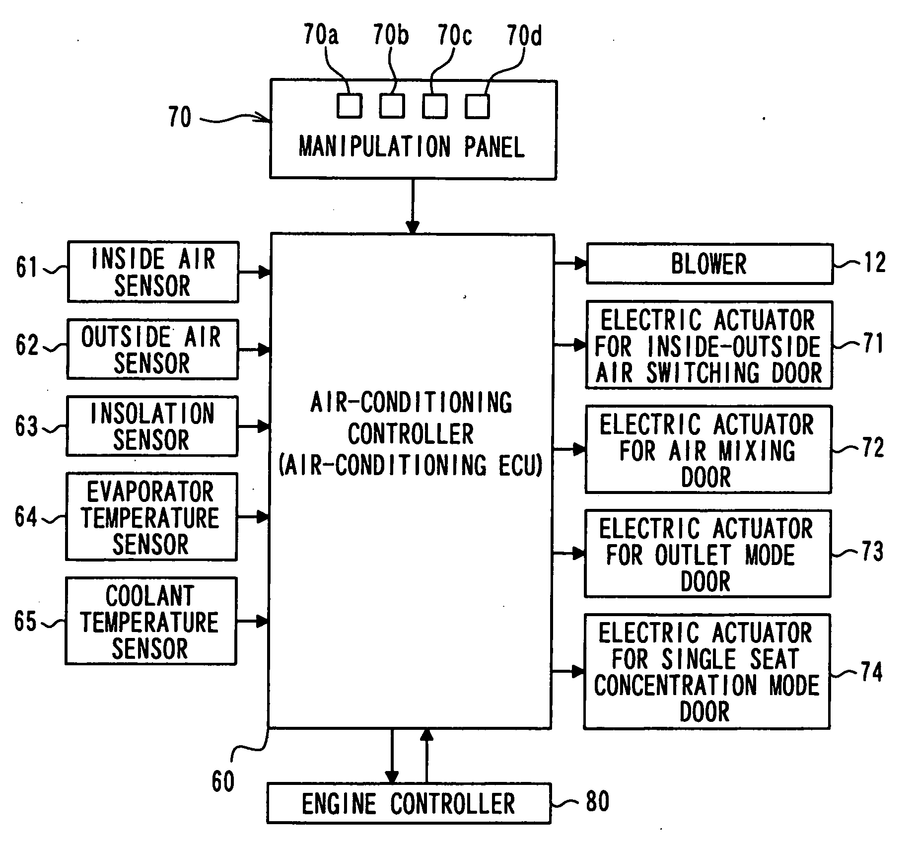
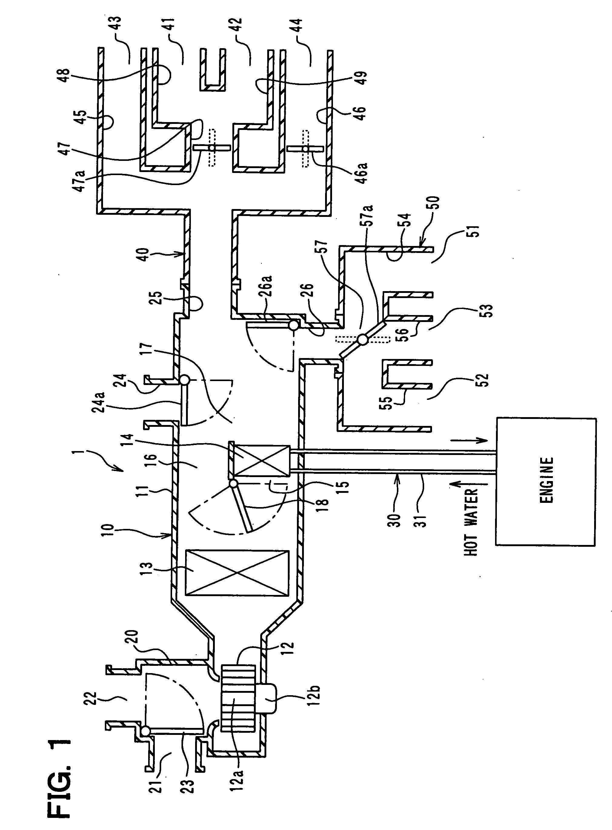
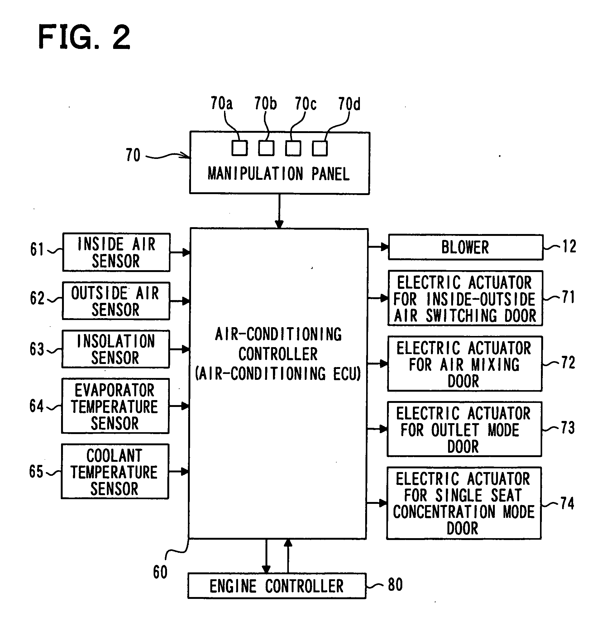
[0135]FIG. 1 shows an entire construction of a vehicular air conditioner according to a first embodiment of the present invention. FIG. 2 shows an electric control section of the vehicular air conditioner of FIG. 1. The vehicular air conditioner according to the present embodiment is mounted in a hybrid vehicle that obtains a driving force for running a vehicle from an engine (internal combustion engine) and an electric running motor.

[0136]The hybrid vehicle according to the present embodiment operates or stops the engine in accordance with a running load of the vehicle. Thus, the hybrid vehicle switches a running state of the vehicle among a state in which the vehicle runs by obtaining the driving force from both of the engine and the electric running motor, a state in which the vehicle runs by stopping the engine and by obtaining the driving force only from the electric running motor, and other states. Thus, the hybrid vehicle improves a vehicle fuel consumption as compared to an ...

second embodiment

[0201]Next, a second embodiment of the present invention will be described. FIG. 6 shows an entire construction of a vehicular air conditioner according to the second embodiment. In the present embodiment, an air volume adjusting door 45a for adjusting an air blowing amount blown from the side face outlet 43 on the driver seat side is provided inside the face duct 40 of the construction of FIG. 1 explained in the description of the first embodiment. The air volume adjusting door 45a is provided in the passage 45 connecting to the side face outlet 43 on the driver seat side.

[0202]The air-conditioning controller 60 according to the second embodiment performs air-conditioning control similar to the air-conditioning control of the first embodiment. The air-conditioning controller 60 according to the second embodiment further performs adjustment of the air volume of the side face outlet 43 on the driver seat side when the air-conditioning controller 60 performs the adjustment of the open...

third embodiment

[0206]Next, a third embodiment of the present invention will be described. FIG. 7 is a schematic diagram showing a vehicular air conditioner according to the third embodiment. The vehicular air conditioner according to the present embodiment performs air-conditioning control independently between the driver seat side and the passenger seat side.

[0207]More specifically, in the vehicular air conditioner according to the present embodiment, partition walls 11a, 11b are provided in the casing 11 of the vehicle compartment air-conditioning unit 10 for partitioning the air passageway downstream of the evaporator 13 with respect to the airflow direction into an air passageway 111 on the driver seat side and an air passageway 112 on the passenger seat side. The heater core 14 is arranged to straddle both of the air passageway 111 on the driver seat side and the air passageway 112 on the passenger seat side

[0208]Further, a heating cold air passageway 15a, a cold air bypass passage 16a and a ...


PUM


Abstract

When there is no occupant in seats other than a driver seat during a foot mode, an air-conditioning controller executes a single seat concentration mode to prevent blowing of warm air to a passenger seat and a backseat by closing foot outlets on a passenger seat side and a backseat side. In this case, in order to maintain an air volume blown from the foot outlet on a driver seat side when the controller changes the mode from the normal foot mode to the single seat concentration mode, the controller sets a blower level to be lower than in the case of the normal foot mode with respect to the same target blown air temperature. Thus, an electric power consumed by an electric motor of a blower can be reduced, thereby realizing energy saving.

Description

CROSS REFERENCE TO RELATED APPLICATION[0001]This application is based on and incorporates herein by reference Japanese Patent Applications No. 2009-260765 filed on Nov. 16, 2009, No. 2009-261753 filed on Nov. 17, 2009, No. 2010-52041 filed on Mar. 9, 2010, and No. 2010-73143 filed on Mar. 26, 2010.BACKGROUND OF THE INVENTION[0002]1. Field of the Invention[0003]The present invention relates to a vehicular air conditioner.[0004]2. Description of Related Art[0005]There is a vehicular air conditioner that turns blown air toward a driver seated in a driver seat when no passenger is in a passenger seat, whereby much air-conditioning wind directly hits the driver seated in the driver seat, for example, as described in Patent document 1 (JP-A-H8-25948) or Patent document 2 (JP-A-2000-142081).[0006]In recent years, improvement of fuel consumption of the vehicle has been required, and therefore energy saving of the vehicular air conditioner has been desired.[0007]Patent document 1 describes i...

Claims


Application Information

Patent Timeline
IPC IPC(8): B60H1/00F24F7/00
CPCB60H1/00742Y02T10/88B60H2001/00992B60H2001/00733
Inventor MISUMI, HARUKIKATAOKA, TAKUYAOTA, KOJINISHIKAWA, MICHIOHIRAI, SHINICHIROUSUZUKI, YOSHIAKIHARAGUCHI, AKIHIROKUWADA, KATSUJISAGOU, YASUHIRO
Owner DENSO CORP
Why Eureka
Try Eureka