Seat air conditioning unit

a seat air conditioner and air conditioning technology, applied in the field of seat air conditioners, can solve the problems of difficult to provide a sufficient cooling effect, difficulty in controlling the temperature of the air to be blown from the seat surface, and difficulty in reducing the air flow rate, so as to reduce the power consumption in the draft mode, improve the draft effect, and reduce the effect of pressure loss

Inactive Publication Date: 2006-11-16
DENSO CORP
View PDF13 Cites 60 Cited by
  • Summary
  • Abstract
  • Description
  • Claims
  • Application Information

AI Technical Summary

Benefits of technology

[0008] The present invention is made in view of the foregoing matter, and it is an object of the present invention to provide a seat air conditioning unit having a draft effect by blowing the large volume of air in a transitional state and a cooling or heating effect in a normal operation.
[0012] Accordingly, the ratio of air blown from the first outlet port to the air introduced in the inlet port is changed between the draft mode and the normal mode. Namely, in the draft mode, the volume of air blown from the seat surface is larger than that in the normal mode. Therefore, a draft effect improves. On the other hand, in the normal mode, the air blown from the first outlet port has an air conditioning effect through the first heat exchanger. Further, in the predetermined condition, the heat exchange rate in the heat exchanger unit is smaller than that in the normal mode, and the air volume control device is operated in the draft mode. Accordingly, the large volume of air is blown from the seat surface with reduced power consumption in the draft mode.
[0014] Accordingly, the ratio of air introduced to the first outlet port to the air introduced in the inlet port is changed between the draft mode and the normal mode. Namely, in the draft mode, the volume of air blown from the seat surface is larger than that in the normal mode since the volume of air passing through the bypass passage is increased by the operation of the air volume control device. Accordingly, a draft effect on the seat surface improves. On the other hand, in the normal mode, the air blown from the first outlet port has an air conditioning effect through the first heat exchanger. Further, since the air is introduced to the first outlet port through the bypass passage, a pressure loss reduces. With this, the volume of air blown from the first outlet port increases.

Problems solved by technology

Therefore, it is difficult to blow a sufficient volume of air from the seat surface in the transitional state.
However, the temperature of the air to be blown from the seat surface is not controlled.
Therefore, it is difficult to provide a sufficient cooling effect, particularly, in a normal operation.

Method used


Image

  • Seat air conditioning unit
  • Seat air conditioning unit
  • Seat air conditioning unit

Examples


Embodiment Construction

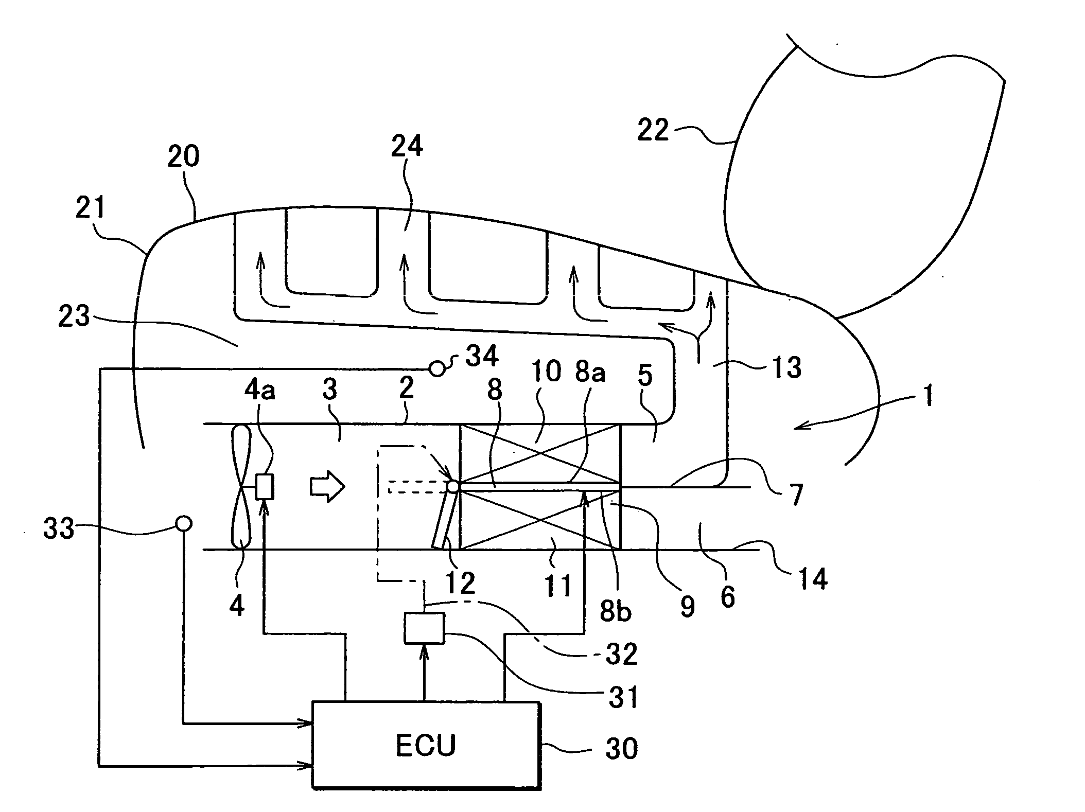
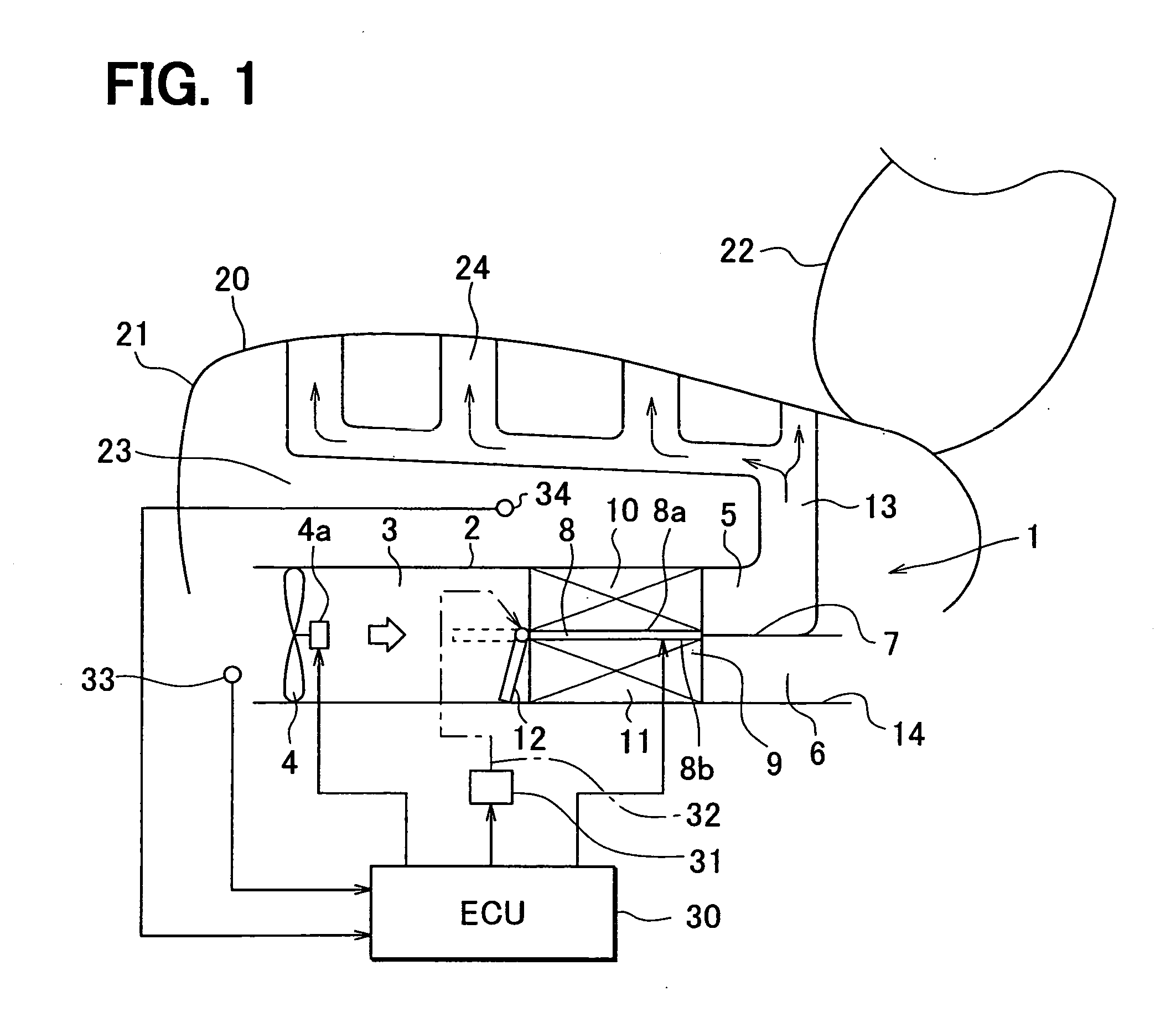
[0033] A first example embodiment of the present invention will now be described with reference to FIGS. 1 to 4. As shown in FIG. 1, a seat air conditioning unit 1 of the first example embodiment is for example mounted to a seat bottom 21 of a seat 20. Alternatively, the seat air conditioning unit 1 can be mounted to a seat back 22.

[0034] The seat air conditioning unit 1 has a duct 2, a blower 4 and a heat exchanger unit 9. The duct 2 forms an inlet port 3 at one end (left end in FIG. 1) and the blower unit 4 is located upstream of the inlet port 3. The heat exchanger unit 9 is located downstream of the blower unit 4 in the duct 2. The blower unit 4 sucks air and blows the air into the duct 2. The seat air conditioning unit 1 is for example used in a vehicle. In this case, the blower unit 4 sucks air inside a passenger compartment. The blower unit 4 is disposed such that the air is fully introduced into a passage space of the duct 2 through the inlet port 3. In FIG. 1, an axial flo...


PUM


Abstract

In an air conditioning unit for a seat, a duct forms a first outlet port through which air is blown to a seat surface and a second outlet port for discharging air. A heat exchanger unit having a thermoelectric effect element is disposed in the duct. An air volume control device is disposed in a duct to control a ratio of air introduced to the first outlet port to air introduced in an inlet port of the duct. In a draft mode, the air volume control device is operated such that the volume of air introduced to the first outlet port is larger than that in a normal mode. In a predetermined condition, the air volume control device is operated in the draft mode and an electric current supply to the thermoelectric effect element is controlled such that a heat exchange rate in the heat exchanger unit is smaller than that in the normal mode.

Description

CROSS REFERENCE TO RELATED APPLICATION [0001] This application is based on Japanese Patent Applications No. 2005-138609 filed on May 11, 2005, No. 2006-46506 filed on Feb. 23, 2006, and No. 2006-46507 filed on Feb. 23, 2006, the disclosures of which are incorporated herein by reference. FIELD OF THE INVENTION [0002] The present invention relates to a seat air conditioning unit that blows air from a seat surface. BACKGROUND OF THE INVENTION [0003] According to a seat air conditioning unit disclosed in Japanese Unexamined Patent Publication No. 10-44756, a temperature of air to be blown from a surface of a seat is increased or reduced through a heat exchanger unit having a Peltier element so as to improve a feeling of a passenger seating on the seat. A flow of air is produced by a blower unit and is introduced to the heat exchanger unit. In the heat exchanger unit, a first heat exchanger is disposed on a heat absorbing side of the Peltier element and a second heat exchanger is dispose...

Claims


Application Information

Patent Timeline
Patent Type & Authority Applications(United States)
IPC IPC(8): F25B21/02F25D23/12
CPCB60N2/5635F25B21/04B60N2/5692B60N2/5685
Inventor ITO, YUJIYAMAMOTO, TAKASHIYOSHIDA, TAKAHIROMIZUTANI, SATOSHITSUJI, YOSHINORI
Owner DENSO CORP
Why Eureka
Try Eureka