
Evaluating method and parameter testing method for optical equipment of dense wavelength division multiplexing (DWDM) system

A dense wavelength division multiplexing and optical equipment technology, applied in the field of optical communication, can solve problems such as the system cannot work normally, the system has a large impact, and the system optical equipment is not found, and achieves the effect of improving the system transmission reliability and the design level.

Active Publication Date: 2012-03-14
ZTE CORP
View PDF3 Cites 0 Cited by
  • Summary
  • Abstract
  • Description
  • Claims
  • Application Information

AI Technical Summary

Problems solved by technology

The business is carried by this phase modulation method, and the optical filter parameters of the equipment have a great impact on the system
The optical equipment that can work normally in the 10Gb / s system can no longer guarantee the normal operation of the system when transmitting 40Gb / s
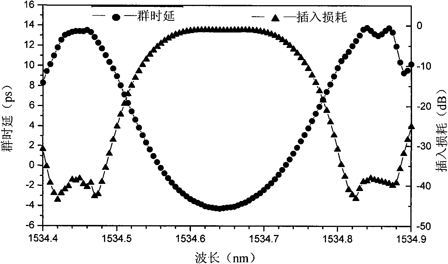
[0003] figure 1 The group delay (Group delay, GR) spectrum of the 50GHz comb optical filter (interleaver) shown, this device can guarantee the normal operation of the system in the 10Gb / s system, but it will introduce excessive cost in the 40Gb / s system , the system does not work properly
[0004] At present, no suitable parameters have been found to regulate high-speed Dense Wavelength Division Multiplexing (DWDM) system optical equipment (mainly refers to optical filters)

Method used


Image

  • Evaluating method and parameter testing method for optical equipment of dense wavelength division multiplexing (DWDM) system
  • Evaluating method and parameter testing method for optical equipment of dense wavelength division multiplexing (DWDM) system
  • Evaluating method and parameter testing method for optical equipment of dense wavelength division multiplexing (DWDM) system

Examples


Embodiment Construction

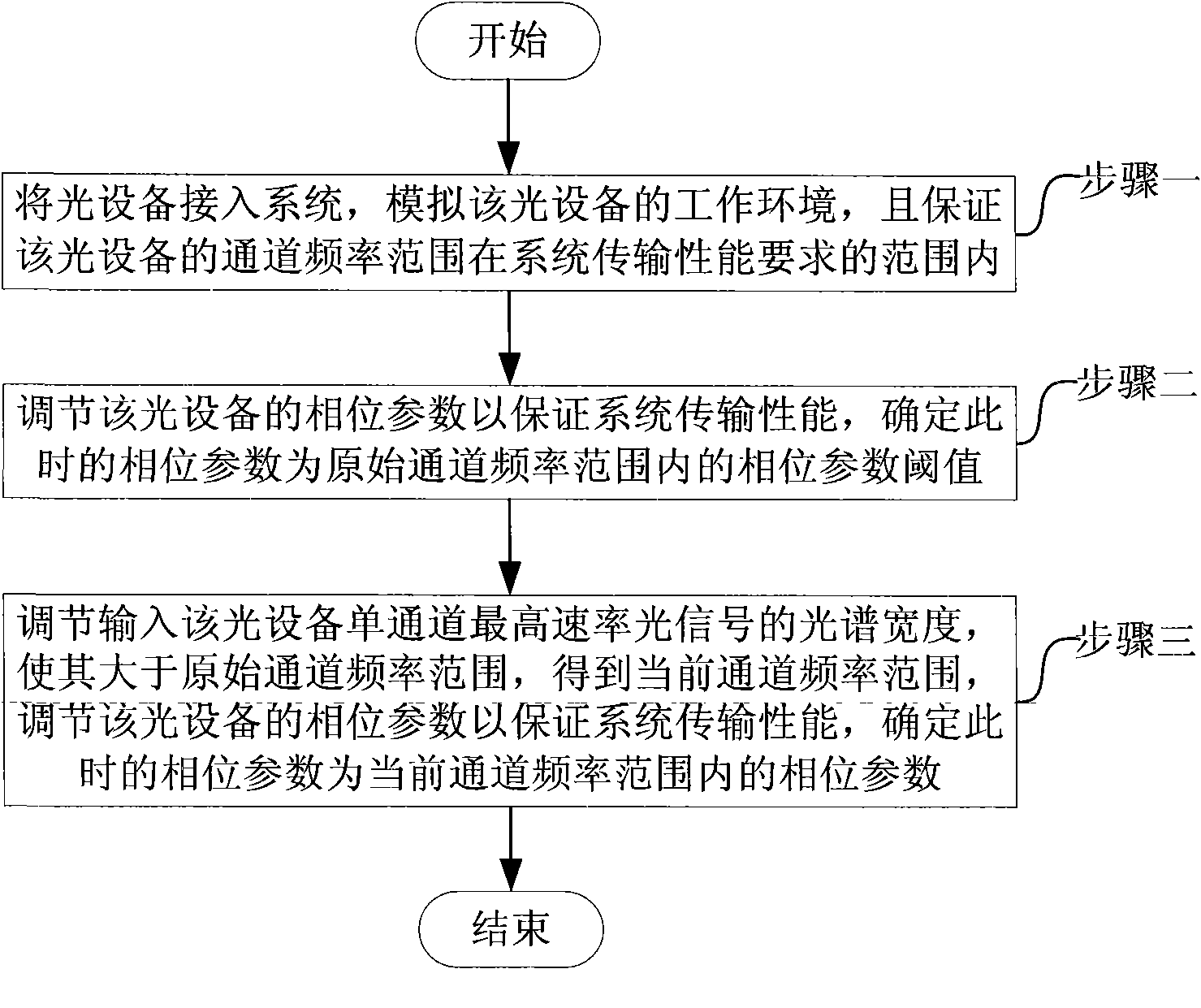
[0024] The present invention provides an evaluation method of optical equipment: determine the phase parameter test value of the optical equipment to be evaluated, compare the phase parameter test value with the phase parameter threshold, and evaluate whether the optical equipment is usable.

[0025] The step of determining the phase parameter test value of the optical device to be evaluated includes: determining the channel frequency range of the optical device, and then determining the phase parameter test value within the channel frequency range. The frequency range of the channel of the optical device can be obtained by reading the frequency range at a substantially flat position on the insertion loss spectrum. The phase parameter of the optical device in the channel frequency range can be determined by the following method: reading the group delay in the channel frequency range from the group delay spectrum of the optical device, and reading the group delay in the channel ...


PUM


Abstract

The invention discloses an evaluating method and a parameter testing method for optical equipment of a dense wavelength division multiplexing (DWDM) system and provides a standard parameter and an evaluating method for the optical equipment of the DWDM system as well as a testing method for the parameter. The evaluating method for the optical equipment comprises the following steps of: determining a phase parameter testing value of the optical equipment to be evaluated; comparing the phase parameter testing value with a phase parameter threshold; and evaluating whether the optical equipment is available or not. The parameter testing method comprises the following steps of: adjusting the phase parameter of the optical equipment within the determined channel frequency range; and when the transmission performance of the system is ensured, taking the phase parameter at the time as a first phase parameter threshold for evaluating the optical equipment within the channel frequency range.

Description

technical field [0001] The invention relates to the field of optical communication, in particular to a dense wavelength division multiplexing system optical equipment evaluation and parameter testing method. Background technique [0002] With the growth of communication bandwidth, the optical transmission system develops rapidly. At present, a Dense Wavelength Division Multiplexing (DWDM, Dense Wavelength Division Multiplexing) system with a single-channel rate of 40 Gb / s and a frequency interval of 50 GHz has been commercially available. Due to the increase of the rate, such as 40Gb / s rate, the original OOK (On-Off Keying) modulation mode has greater transmission damage and its application is limited. DPSK (Differential Phase Shift Keying) or DQPSK (Differential Quadrature Phase Shift Keying) ) and other phase modulation methods are widely used. Services are carried in this phase modulation mode, and the optical filter parameters of the equipment have a great impact on th...

Claims


Application Information

Patent Timeline
IPC IPC(8): H04B10/08H04Q11/00H04J14/02H04B10/07
Inventor 张红宇沈百林
Owner ZTE CORP
Learn More