Boots

A technology for boots and barrels, applied in the directions of boot legs, shoe uppers, clothing, etc., can solve the problems of reduced fit and poor fit, etc.

Active Publication Date: 2012-03-21
DAIWA SEIKO CORPORATION
View PDF3 Cites 3 Cited by
  • Summary
  • Abstract
  • Description
  • Claims
  • Application Information

AI Technical Summary

Problems solved by technology

[0006] In the above-mentioned known technology, since the pressure pad protrudes inwardly on the inner surface of the curved connection portion between the foot cover portion and the tube portion, the pressure force varies depending on the circumfere

Method used


Image

  • Boots
  • Boots
  • Boots

Examples


Embodiment Construction

[0029] Hereinafter, embodiments of the boots of the present invention will be described with reference to the drawings.

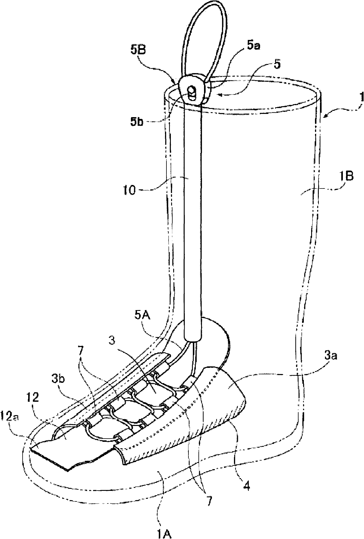
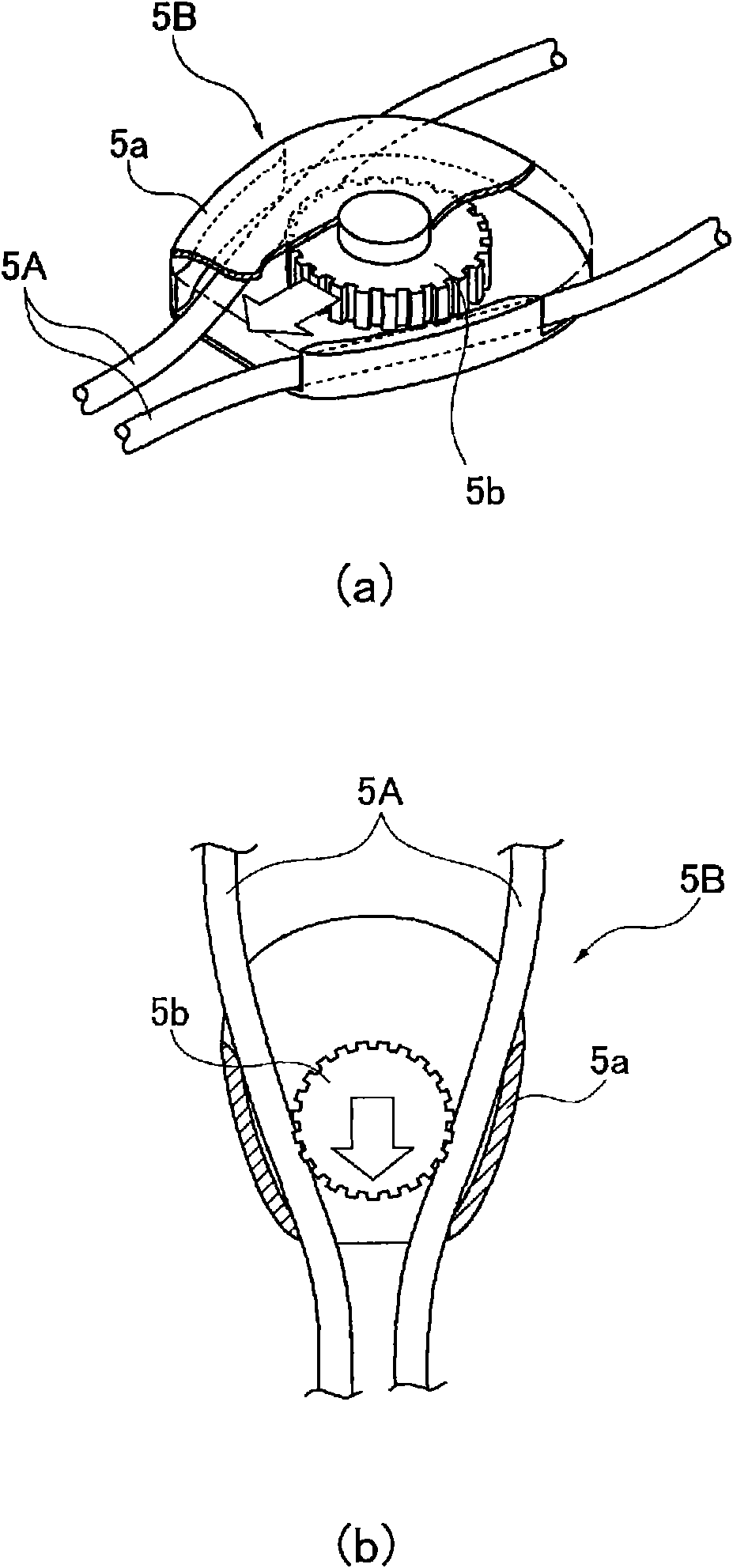
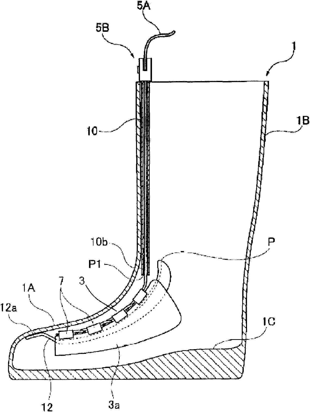
[0030] Figures 1 to 4 It is a figure showing the first embodiment of the boots of the present invention, figure 1 is a diagram showing the internal structure, figure 2 is for figure 1 The figure of the fastener in the shown boots, (a) is a perspective view showing an internal structure, (b) is a planar sectional view, image 3 yes means figure 1 a partial cutaway view of the internal structure of the boot shown, and, Figure 4 is to indicate that it is configured in figure 1 In the diagram of an example of the tubular body in the boot shown, (a) is a cross-sectional view, and (b) is an enlarged view of the tubular body.

[0031] The main body 1 of the boots of this embodiment has: a foot covering part 1A, which is formed in a substantially semi-elliptical cross-section so as to surround the lower part from the ankle region when actually putting the ...


PUM


Abstract

The invention aims to provide a pair of boots with a structure which is perfect fit for a long period of time. Specifically, the boots of the invention comprise foot covering parts (1A) which cover lower portions from the ankle regions; and leg parts (1B) which cover upper portions from the ankle regions. Plate-shaped members (3a) and (3b) are arranged inside the foot covering parts (1A) and are capable of clamping instep portions. Adjusting units (5) are arranged on the leg parts (1B) and are capable of adjusting the clamping state of the instep portions through connection with the plate-shaped members (3a) and (3b).

Description

technical field [0001] The present invention relates to a boot for bad weather or recreational use. Background technique [0002] Generally, boots include: a foot covering part that surrounds the lower part from the ankle area; Since such boots have a large gap between the instep and the foot cover during use, the area from the toe to the heel of the sole tends to hang from the sole of the boot, resulting in poor fit and difficulty in walking. [0003] In order to solve the above-mentioned problems, Patent Document 1 discloses boots in which an elastic pressure pad such as a sponge is provided on the inner surface of the curved connection portion between the instep side foot cover portion and the tube portion to be inserted. [0004] According to such boots, since there is no space between the instep and the foot covering portion, the heel does not hang from the boot sole during walking, and the fit feeling can be improved. [0005] Patent Document 1: Japanese Patent Laid-...

Claims


Application Information

Patent Timeline
IPC IPC(8): A43B3/02A43B23/02A43C11/00
CPCA43B3/02A43C7/08A43C11/12A43C11/165
Inventor 山口信之
Owner DAIWA SEIKO CORPORATION
Why Eureka
Try Eureka