

Unfolding control device for three-dimensional inflatable unfolding truss structure
A technology of inflatable deployment and truss structure, applied in directions such as artificial satellites, can solve the problem of no three-dimensional inflatable deployment truss structure, etc., and achieve the effect of reducing disturbance
- Summary
- Abstract
- Description
- Claims
- Application Information
AI Technical Summary
Problems solved by technology
Method used
Image

Examples
specific Embodiment approach 1
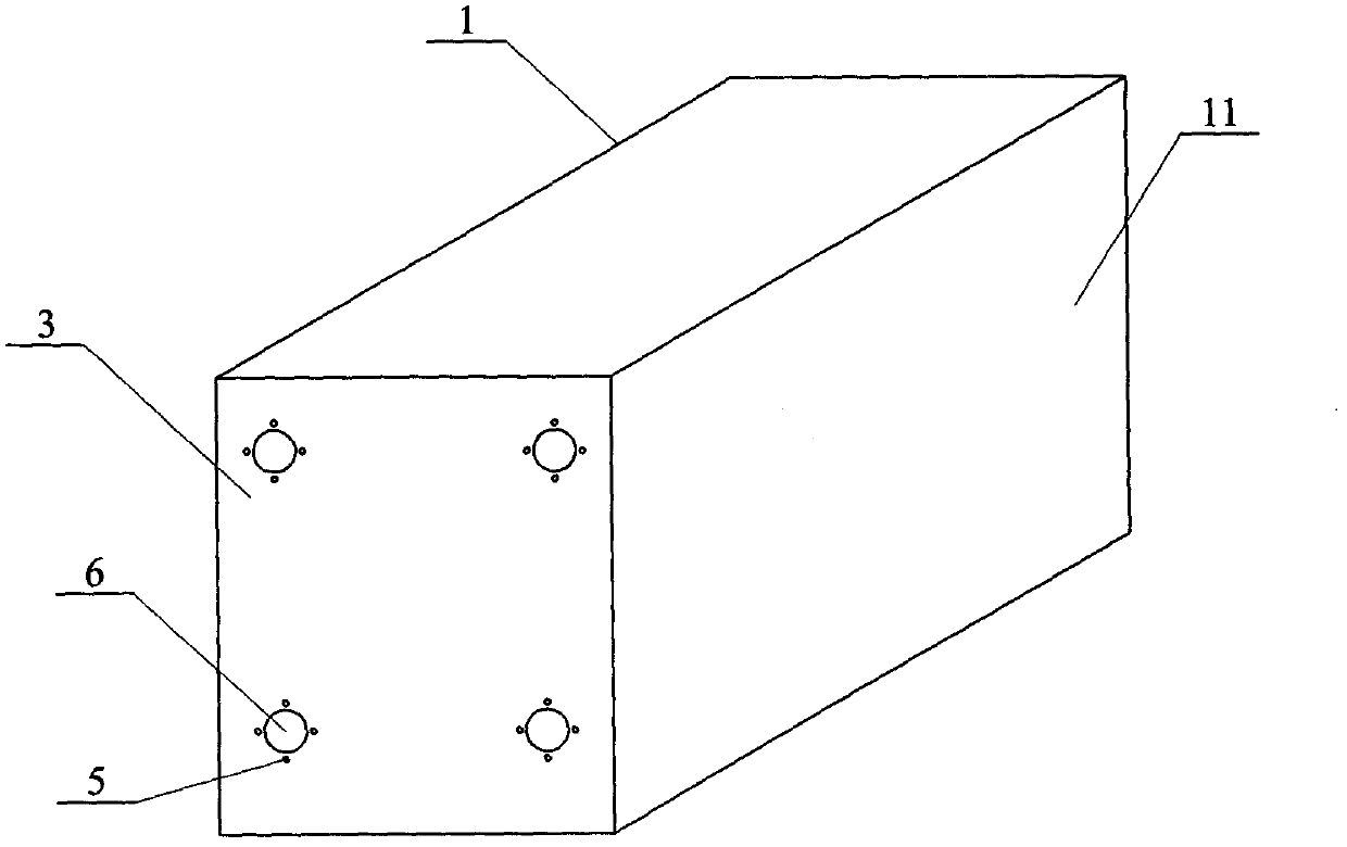
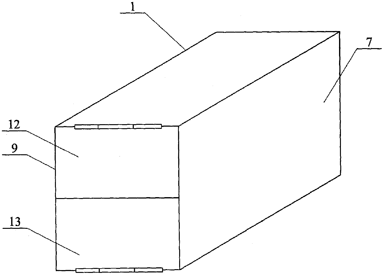
[0018] Specific implementation mode one: see Figure 1 to Figure 10 , the deployment control device of a three-dimensional inflatable unfolded truss structure described in this embodiment includes a folding loading box 1 and an eight-column spring sheet array 2, the folding loading box 1 is a rectangular parallelepiped thin-walled box structure, and the folding loading box 1 The front side wall is a box cover 9, the front end of the folding loading box 1 is the expanded extension end of the inflatable unfolding truss 4, the rear side wall 3 of the folding loading box 1 is the fixed end of the inflatable unfolding truss 4, and the rear side of the folding loading box 1 The wall 3 is provided with a plurality of fixing screw holes 5 and a plurality of through holes 6, the plurality of fixing screw holes 5 are used to fix the inflatable unfolding truss 4, and the inflation conduit used when the inflatable expanding truss 4 is inflated and expanded passes through the through holes ...
specific Embodiment approach 2
[0019] Specific implementation mode two: see Figure 3 to Figure 10 , as the deployment control device of a three-dimensional inflatable unfolded truss structure described in Embodiment 1, each folded section of each main support tube 10 arranged along the length direction on the inflated unfolded truss 4 is constrained to be located in the same row of spring leaf arrays 2 between two adjacent rectangular spring pieces 8.
[0020] The main support tubes 10 arranged along the length direction in the inflatable deployment truss 4 in this embodiment are folded in a Z shape when folded. All the main support tubes 10 arranged along the length direction of the inflatable deployment truss 4 are folded into a Z-shaped folded state.
specific Embodiment approach 3
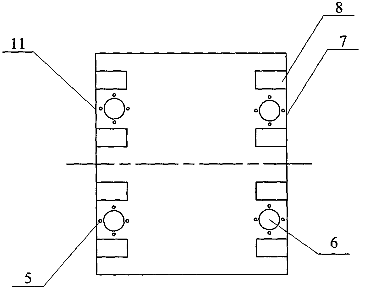
[0021] Specific implementation mode three: see Figure 1 ~ Figure 4 and Figure 7 ~ Figure 10 Illustrate, as the deployment control device of a three-dimensional inflatable deployment truss structure described in Embodiment 1 or 2, the number of multiple through holes 6 is four, and the four through holes 6 are located on the rear side wall 3 of the folding loading box 1 The top is arranged in a rectangular shape, and the number of multiple fixing screw holes 5 is sixteen. The sixteen fixing screw holes 5 are divided into four groups, and the four groups of fixing screw holes are set in one-to-one correspondence with the four through holes 6. Each group of fixing screw holes The number is four, and the four fixing screw holes 5 in each set of fixing screw holes are uniformly arranged on the outer periphery of the corresponding through holes 6 . The purpose of this design is to fix an inflatable expansion main support pipe 10 of the inflatable expansion truss 4, so that sixtee...
PUM
 Abstract
Description
Claims
Application Information