Steel bar binding machine

A technology of steel bar binding and body, which is applied in the processing of building materials, construction, building structure, etc., can solve the problems of slow construction speed and high labor intensity.

Pending Publication Date: 2018-01-19
福建谊和天宸科技有限公司
View PDF7 Cites 9 Cited by
  • Summary
  • Abstract
  • Description
  • Claims
  • Application Information

AI Technical Summary

Problems solved by technology

[0002] In the construction industry, steel bars are equivalent to the bones of the human body, which play the role of supporting and tying the building body. A large number of steel bars need to be fixed in sequence according to the engineering drawings before pouring concrete, so that the steel bar skeleton can be fixed reliably. Traditional steel bar binding is still used. Manual operation is not only labor-intensive, but also the construction speed is slow

Method used


Image

  • Steel bar binding machine
  • Steel bar binding machine
  • Steel bar binding machine

Examples


Embodiment Construction

[0024] The content of the present invention will be described in detail below in conjunction with the accompanying drawings and embodiments of the description:

[0025] Such as Figures 1 to 11 Shown is a schematic diagram of an embodiment of a steel bar binding machine provided by the present invention.

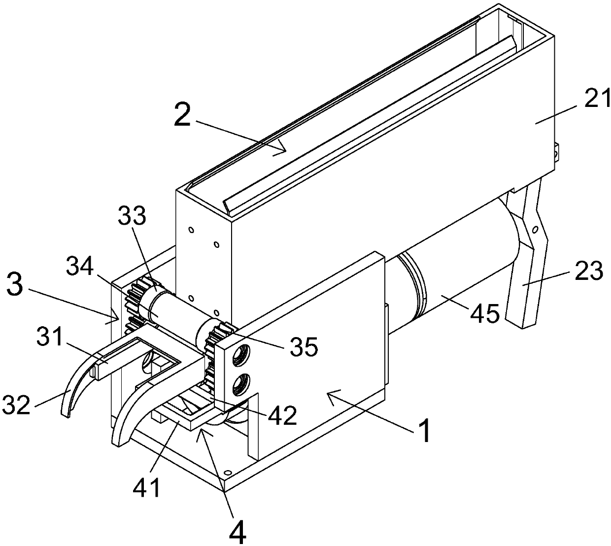
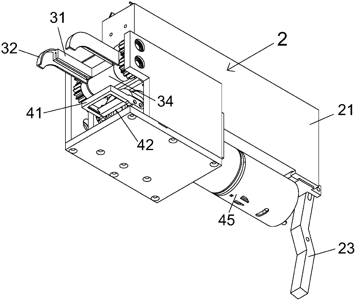
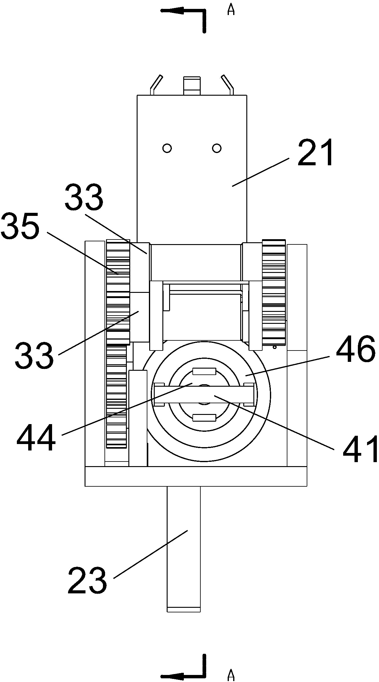
[0026] A steel bar binding machine, which includes a body 1, a wire storage mechanism 2 for storing U-shaped wire binding 5, and a wire output mechanism that communicates with the wire storage mechanism 2 and bends the two free ends of the U-shaped binding wire 5 to one side 3 and the binding mechanism 4 that is correspondingly arranged on the bending side of the U-shaped binding wire 5 and tightens the two free ends of the U-shaped binding wire 5 .

[0027] The present invention adopts buckle binding method, which is used for binding the junction of horizontal and vertical steel bars.

[0028] The binding material used in the present invention is a prefabricated U-shaped ...


PUM


Abstract

The invention relates to a steel bar binding machine. The steel bar binding machine comprises a machine body, a wire storage mechanism, a wire outlet mechanism and a binding mechanism; the wire storage mechanism is used for storing a U-shaped binding wire; the wire outlet mechanism communicates with the wire storage mechanism and bends the two free ends of the U-shaped binding wire to one side; and the binding mechanism is arranged on the bent side of the U-shaped binding wire correspondingly and tightly twists the two free ends of the U-shaped binding wire. The steel bar binding machine is high in automation degree and has the advantages that the steel bar binding machine is provided with the wire storage mechanism, the wire outlet mechanism and the binding mechanism, the U-shaped bindingwire can be bent automatically, and the free ends of the U-shaped binding wire can be tightly twisted automatically, the automation degree is high, and the binding efficiency of steel bars is improved greatly.

Description

technical field [0001] The invention relates to a steel bar binding machine. Background technique [0002] In the construction industry, steel bars are equivalent to the bones of the human body, which play the role of supporting and tying the building body. A large number of steel bars need to be fixed in sequence according to the engineering drawings before pouring concrete, so that the steel bar skeleton can be fixed reliably. Traditional steel bar binding is still used. Manual operation is not only labor-intensive, but also slow in construction speed. Contents of the invention [0003] The object of the present invention is to provide a kind of steel bar binding machine with high degree of automation. [0004] The purpose of the present invention is achieved through the following technical solutions: a steel bar binding machine, which includes a body, a wire storage mechanism for storing U-shaped wires, connected with the wire storage mechanism and bending the two free...

Claims


Application Information

Patent Timeline
Patent Type & Authority Applications(China)
IPC IPC(8): E04G21/12
Inventor 陈兵
Owner 福建谊和天宸科技有限公司
Why Eureka
Try Eureka