Gas chromatograph

A gas chromatograph and shell technology, applied in the field of gas chromatograph, can solve the problems of shell cooling and inability to cool the first motor efficiently

Active Publication Date: 2012-03-21
SHIMADZU SEISAKUSHO CO LTD
View PDF9 Cites 4 Cited by
  • Summary
  • Abstract
  • Description
  • Claims
  • Application Information

AI Technical Summary

Problems solved by technology

However, since the air warmed by the heat of the outer shell of the thermostat 10 is used, the first motor 40 and the second motor 41 cannot be cooled efficiently.
In addition, although the second vane 33 is rotated at

Method used


Image

  • Gas chromatograph
  • Gas chromatograph
  • Gas chromatograph

Examples


Embodiment approach

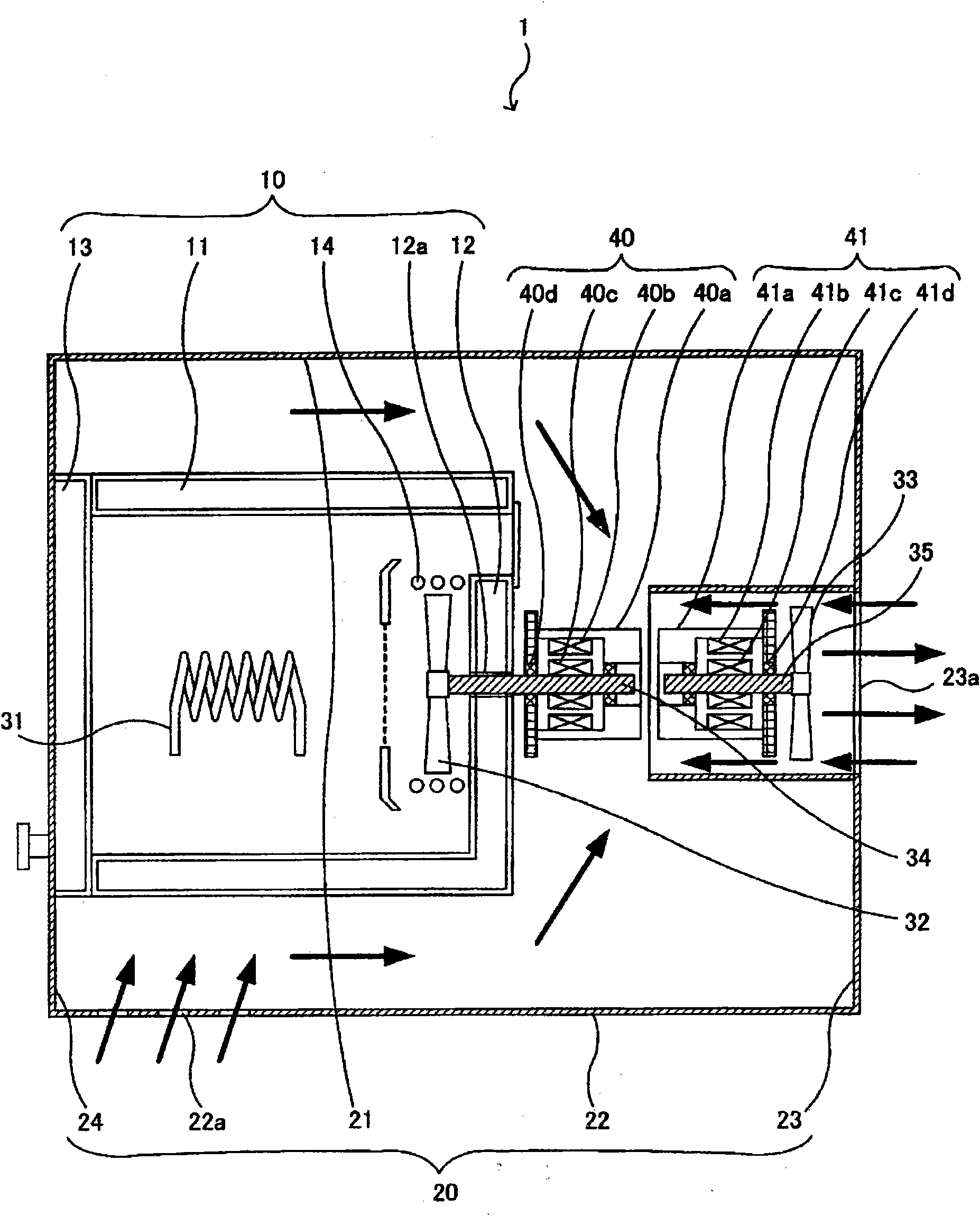
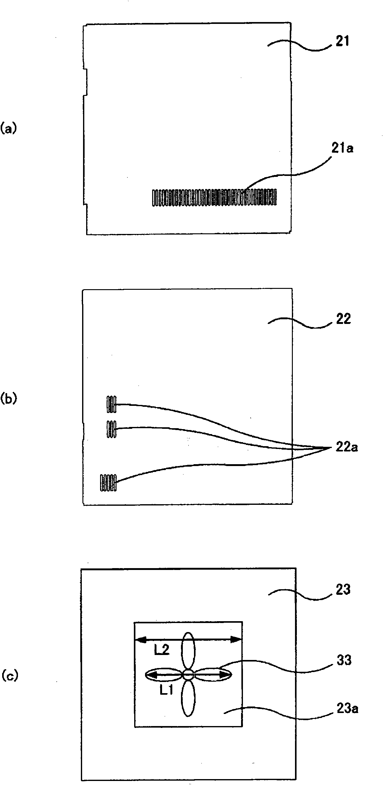
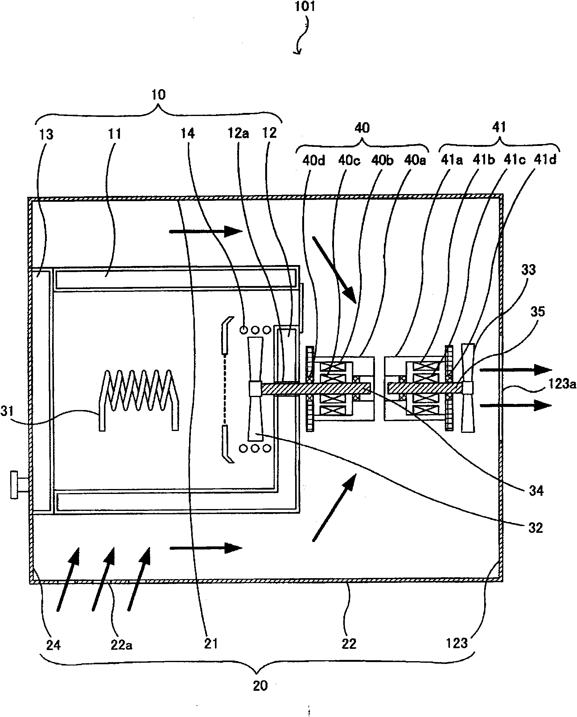
[0055] (1) In the above-mentioned gas chromatograph 1, the structure in which the second vane 33 and the second motor 41 are arranged inside the tube 23b is shown, but it may be configured such that the second vane, the second motor 41 are arranged inside the tube. Such a structure of the second electric motor and the first electric motor.

[0056] (2) In the gas chromatograph 1 described above, the first motor 40 and the second motor 41 are separately provided, but it is also possible to configure the first motor by connecting the first shaft and the second shaft. One motor integrated with the second motor.

[0057] The present invention can be used in a gas chromatograph for accommodating a chromatographic column in an incubator and adjusting the temperature of the chromatographic column.


PUM


Abstract

Provided is a gas chromatograph capable of properly cooling a motor and a casing. The gas chromatograph comprises a thermostat (10) which is configured inside a casing (20) in such a manner to be spaced from walls; a first shaft (34) which, with a rod shape extended along a predetermined direction, has one end portion connected with a first blade (32) and is rotated via a first electric motor (40) around a central shaft in the predetermined direction; and a second shaft (35) which, with a rod shape extended along the predetermined direction, has one end portion connected with a second blade (33) and is rotated via a second electric motor (41) around the central shaft in the predetermined direction. To allow air to flow between the casing (20) and the thermostat (10) along the predetermined direction, the front portion of the casing (20) is provided with front opening portions (21a, 22a), and the rear portion of the casing (20) is provided with a rear opening portion (23a). In a plane perpendicular to the predetermined direction, the area of the rear opening portion (23a) is larger than the rotation area of the second blade (33). A cylindrical pipe (23b) is formed and is extended along the predetermined direction from the edge portion of the rear opening portion (23a).

Description

technical field [0001] The invention relates to a gas chromatograph which houses a chromatographic column in a constant temperature box to adjust the temperature of the chromatographic column. Background technique [0002] In a gas chromatograph, the sample gas squeezes the carrier gas from the inlet end of the chromatographic column and is introduced into the chromatographic column. Thereby, various measurement substances contained in the sample gas are separated in the direction of the time axis while passing through the column, and then reach the outlet end of the column. At this time, in order to allow the sample gas to pass through the column at a predetermined temperature, a gas chromatograph (such as , refer to Patent Document 1). [0003] image 3 It is a sectional view showing an example of a conventional gas chromatograph. in addition, Figure 4 (a) is image 3 Left side view of the gas chromatograph shown, Figure 4 (b) is image 3 Right side view of the gas ...

Claims


Application Information

Patent Timeline
IPC IPC(8): G01N30/54
Inventor 寺井靖典
Owner SHIMADZU SEISAKUSHO CO LTD
Why Eureka
Try Eureka