Rotating electric machine

A technology for rotating electrical machines and rotors, applied in electromechanical devices, electrical components, electrical components, etc., to solve problems such as inability to distribute properly

Active Publication Date: 2020-12-04
HONDA MOTOR CO LTD
View PDF6 Cites 1 Cited by
  • Summary
  • Abstract
  • Description
  • Claims
  • Application Information

AI Technical Summary

Problems solved by technology

[0006] However, in the rotating electric machine described in Patent Document 1, since the cooling medium discharged from the opening provided in the end plate and the outer edge part flows in a common flow path provided in the rotor core, it may not be properly distributed.

Method used


Image

  • Rotating electric machine
  • Rotating electric machine
  • Rotating electric machine

Examples


Embodiment Construction

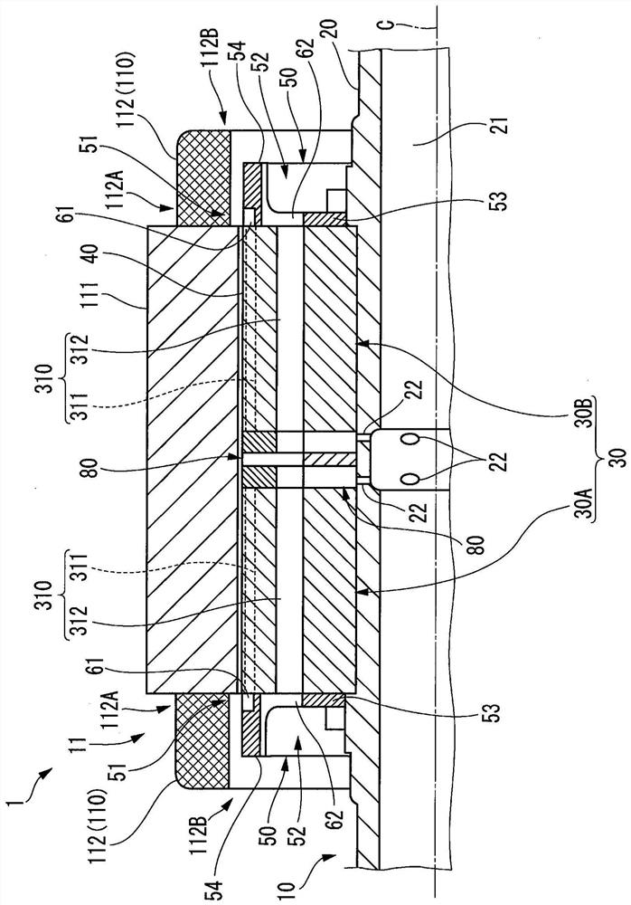
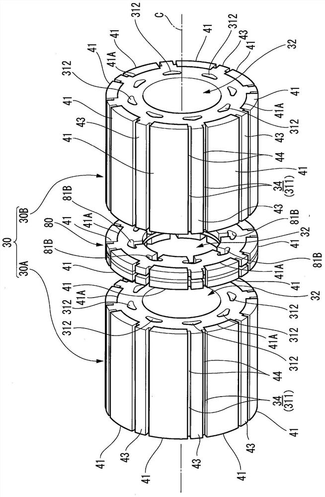
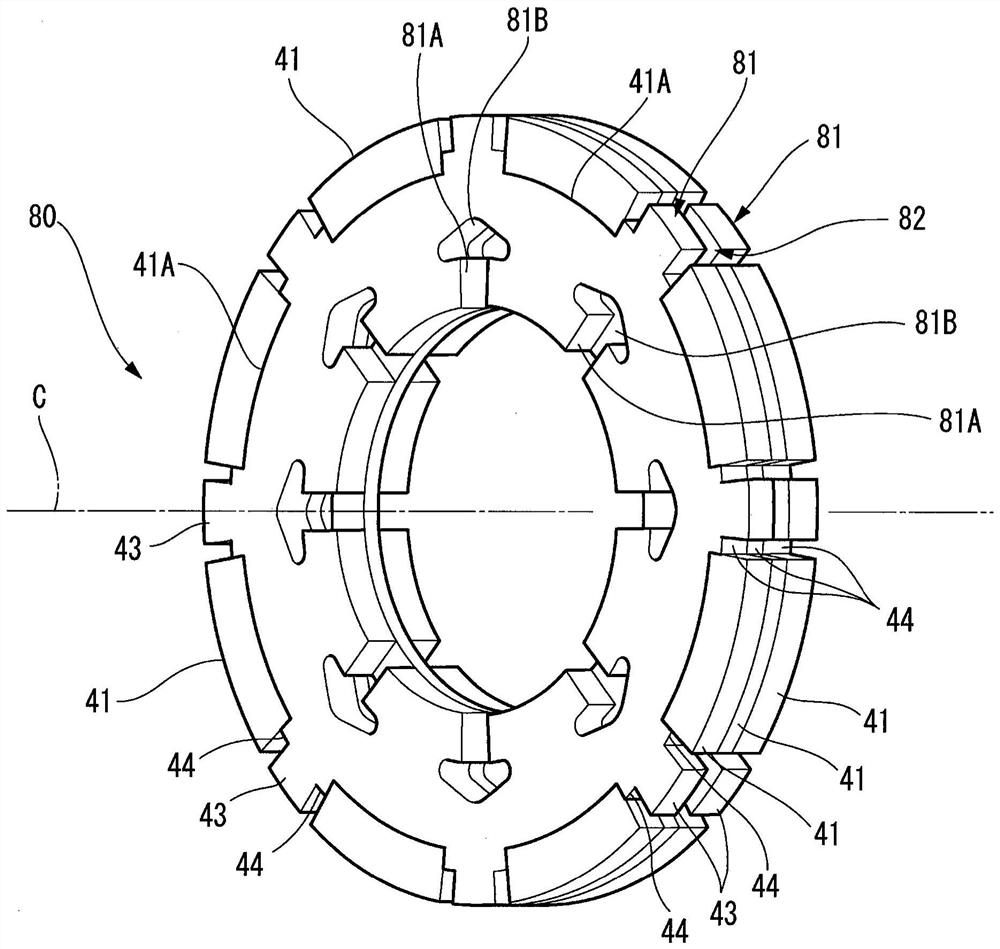
[0069] Hereinafter, an embodiment of a rotating electrical machine according to the present invention will be described with reference to the drawings.

[0070] In the following description, the rotation axis C refers to the axis at the center when the rotor 10 or the rotor shaft 20 of the rotating electric machine rotates, and the axial direction refers to a direction along the rotation axis C. In addition, the term "circumferential direction" refers to a direction in which a circle is drawn around the point when the rotation axis C is viewed as a point and follows the circumference of the circle. On the other hand, when it is called a radial direction, it means a direction from a point to a circle or a direction from a circle to a point. When called radially outward, it refers to the direction from the point toward the circle. When called radially inward, it refers to the direction from the circle toward the point. In addition, thick arrows in the figure conceptually repre...


PUM


Abstract

Provided is a rotating electric machine that is capable of appropriately cooling a coil end portion. The rotating electric machine (1) is provided with a rotor (10) and a stator (11) which face each other with a prescribed gap therebetween in the radial direction. A rotor (10) is provided with: a rotor core (30) having a first cooling medium flow path (311) and a second cooling medium flow path (312); and an end plate (50) disposed on at least one side in the axial direction of the rotor core. A stator is provided with: a stator core (111); and a coil end portion (112) protruding from at leastone axial side of the stator core. The end plate has: a root-side cooling medium supply unit (51) that communicates with the first cooling medium flow path and supplies a cooling medium to a root region (112A) of the coil end; and a tip-side cooling medium supply unit (52) that communicates with the second cooling medium flow path and supplies a cooling medium to a tip region (112B) of the coil end.

Description

technical field [0001] The present invention relates to a rotating electrical machine mounted on an electric vehicle or the like. Background technique [0002] In recent years, rotating electric machines are used in hybrid vehicles or EV vehicles. When the rotating electrical machine rotates, since the temperature rise of the coil which greatly affects the performance of the rotating electrical machine occurs, appropriate cooling is required. [0003] In Patent Document 1, a liquid coolant is discharged from a coolant flow channel penetrating the rotor core, and the liquid coolant is sprayed and rotated along the inner peripheral surface of a bowl-shaped end plate, thereby supplying the coolant to the coil ends of the stator. In addition, it is described that the cooling medium flowing in the flow path of the rotor core is discharged from the opening provided in the end plate and the outer edge portion of the end plate. [0004] prior art literature [0005] Patent Docume...

Claims


Application Information

Patent Timeline
Patent Type & Authority Applications(China)
IPC IPC(8): H02K1/32H02K3/24H02K9/19
CPCH02K1/32H02K3/24H02K9/19H02K1/278
Inventor 涌井隆至藤田泰宽
Owner HONDA MOTOR CO LTD
Why Eureka
Try Eureka