Optical sheet with laminated double-sided light guide plate

A technology of optical sheets and light guide plates, applied in the field of optical sheets, can solve problems such as limited single-sided light guide plates

Inactive Publication Date: 2012-03-21
SKC HAAS DISPLAY FILMS CO LTD
View PDF3 Cites 2 Cited by
  • Summary
  • Abstract
  • Description
  • Claims
  • Application Information

AI Technical Summary

Problems solved by technology

Takada et al. (WO2006 / 098479) disclose a method of manufacturing thick LGPs using an extrusion casting process, but this method is also limited to the manufacture of single-sided LGPs
Thus, while solutions have been proposed for a particular light guide plate and method of making the plate by extrusion, roll-to-roll operations, there is still the possibility of using a single-pass extrusion casting process to efficiently produce The demand for double-sided light guide plate

Method used


Image

  • Optical sheet with laminated double-sided light guide plate
  • Optical sheet with laminated double-sided light guide plate
  • Optical sheet with laminated double-sided light guide plate

Examples


Embodiment 1

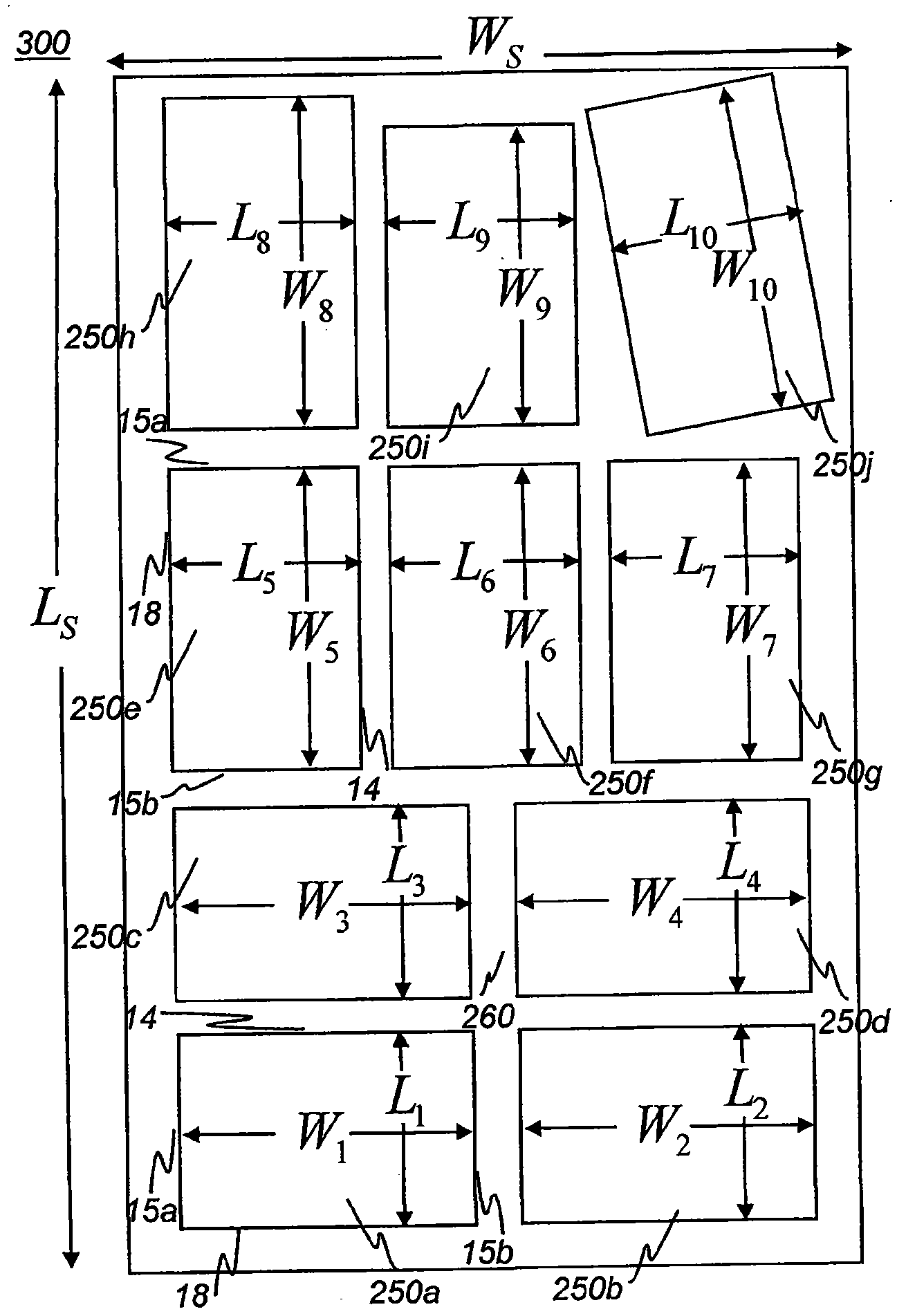
[0070] The optical sheet 300 has a length Ls≈957mm, a width Ws≈343mm, and a thickness Ds ranging from 0.1mm to 0.7mm. There are four light guide plate patterns on the optical sheet 300, each having the same length varying between 150mm to 240mm and width varying between 150mm to 320mm. Since all four light guide plates were produced together in a roll-to-roll process, each light guide plate was produced within 1 second at a processing line speed of 250 mm per second. It is conceivable that for a large number of small light guide plates on the same optical sheet 300 and the same patterned roller, for example, the length and width dimensions are about 20mm, and at the same processing line speed, each light guide plate produced requires The time will be shorter.

Embodiment 2

[0072] The optical sheet 300 has a length Ls≈1436mm, a width Ws≈686mm, and a thickness Ds ranging from 0.1mm to 0.7mm. There are 14 light guide plate patterns on the optical sheet 300, each of which has the same length varying from 150mm to 240mm and width varying from 150mm to 320mm.

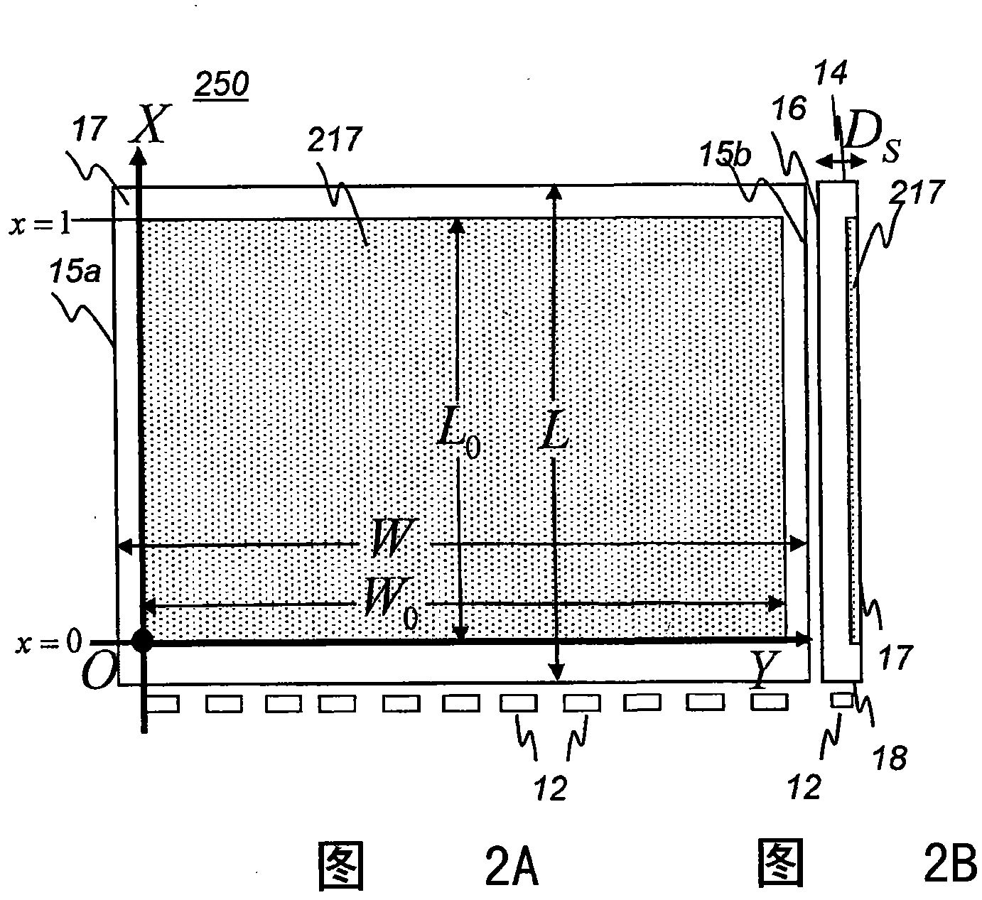
[0073] The above 14 light guide plate patterns have one or more of the following features. In one aspect, at least two of the 14 light guides have different lengths. In another aspect, at least two of the 14 light guide plates have different widths. On the other hand, at least one of the 14 light guide plates has the same width direction as the optical sheet 300 . E.g, figure 1 The light guide plate 250a is shown with W 1 Indicates the width direction of the optical sheet 300 with W S The indicated width direction is parallel. In another aspect, at least one of the 14 light guide plates has a width direction perpendicular to the optical sheet 300 . For example, the light guide plate 250f...

Embodiment 3

[0077] The optical sheet 300 has a length Ls≈1436mm, a width Ws˜980mm, and a thickness Ds ranging from 0.1mm to 0.7mm. There are 21 light guide plate patterns on the optical sheet 300, each having a length varying between 150mm to 240mm and a width varying between 150mm to 320mm.

[0078] When the optical sheet 300 is manufactured at a processing speed of 152mm / sec, it takes about 9.4 seconds to manufacture one optical sheet 300 including 21 light guide plates. An average of less than 0.5 seconds to manufacture a light guide plate, the speed is much higher than the possible traditional injection molding method to produce the same light guide plate.


PUM

PropertyMeasurementUnit
lengthaaaaaaaaaa
widthaaaaaaaaaa
thicknessaaaaaaaaaa

Abstract

The present invention provides an optical sheet (300b) having a plurality of light guide plate patterns, each light guide plate pattern having a micro-patterned output surface for emitting light, and a micro-patterned bottom surface opposing to the output surface. The steps comprise, extruding a first resin (450a) into the nip between a first pressure roller (478a) and a first patterned roller (480a) to form a first layer (410a) at a first patterned roller surface temperature T1 and a first nip pressure P1, the first layer having an unpatterned surface and a patterned surface, the patterned surface having a micro-pattern transferred from the first patterned roller; extruding a second resin (450b) into the nip between a second pressure roller (478b) and a second patterned roller (480b) to form a second layer (410b) at a second patterned roller surface temperature T2 and a second nip pressure P2, the second layer having an unpatterned surface and a patterned surface, the patterned surface having a micro-pattern transferred from the second patterned roller and laminating (490) the first layer and the second layer at their unpatterned surfaces to form the optical sheet comprising a plurality of light guide plate patterns.

Description

field of invention [0001] The present invention generally relates to an optical sheet, and more particularly, to an optical sheet having a double-sided light guide plate and a manufacturing method thereof. Background technique [0002] Liquid crystal displays (LCDs) continue to improve in cost and performance, making them the display technology of choice for many computer, instrumentation, and entertainment applications. Conventional LCD mobile phones, laptops, monitors comprise a light guide plate which receives the light emitted from the light source and redistributes it more or less uniformly through the LCD. The thickness of the existing light guide plate is generally in the range of 0.8mm to 2mm. The light guide must be of sufficient thickness to cooperate effectively with the light source, typically a CCFL or some LED, and then direct as much light as possible to the viewer. Meanwhile, it is difficult and expensive to manufacture a light guide plate with a thickness ...

Claims


Application Information

Patent Timeline
Patent Type & Authority Applications(China)
IPC IPC(8): G02B6/00B29C47/00B29C48/08B29C48/21
CPCB29C47/065G02B6/0068B29C43/222G02B6/0036B29C43/28B29C47/0057G02B6/0065B29D11/00663B29C2947/92704B29K2995/0018B29C47/004B29C47/0021B29C2948/92704B29C48/08B29C48/0011B29C48/0018B29C48/21G02B5/04G02B6/00G02F1/1335B29C59/04
Inventor J·格林纳X-D·米M·R·兰德瑞H·雷李柱贤
Owner SKC HAAS DISPLAY FILMS CO LTD
Why Eureka
Try Eureka