

Zoom optical system and shooting device
An optical system and lens group technology, applied in optics, optical components, components of TV systems, etc., can solve the problems of difficulty in miniaturization and cost reduction, large amount of movement of the second lens group, insufficient chromatic aberration correction, etc. Achieve the effect of less image clarity, small F value, and good chromatic aberration correction
- Summary
- Abstract
- Description
- Claims
- Application Information
AI Technical Summary
Problems solved by technology
Method used
Image

Examples
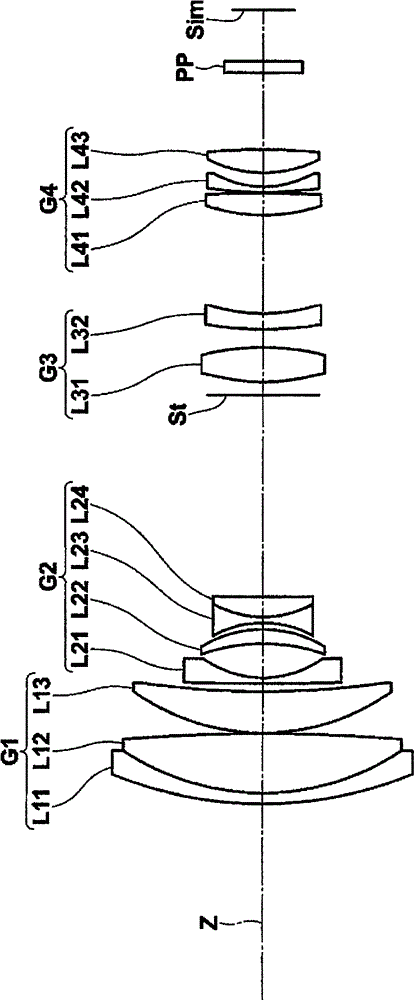
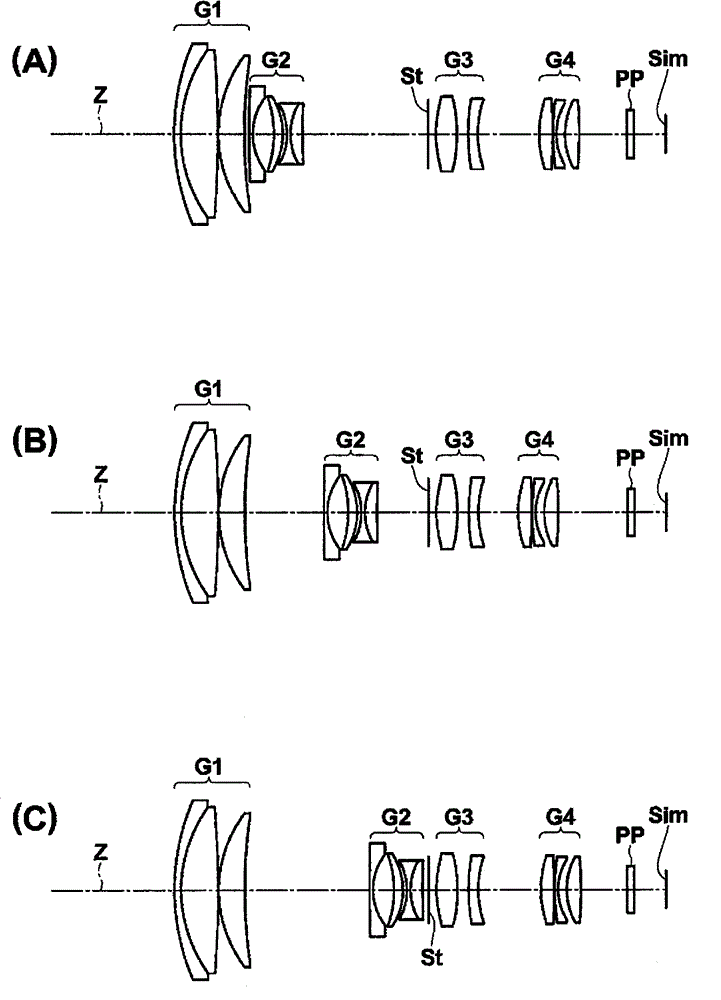
Embodiment 1
[0134] Example 1 Basic Lens Data
[0135]
[0136]
[0137] Table 2
[0138] Embodiment 1 and data related to variable power
[0139]
wide angle end
middle
telephoto end
Variable 1
1.041
16.622
26.261
Variable 2
26.476
10.868
1.299
Variable 3
12.937
8.392
13.194
Variable 4
10.000
14.545
9.743
f
8.159
25.293
77.756
FNo.
1.70
1.93
2.18
2ω
56.74
18.23
5.82
[0140] table 3
[0141] Embodiment 1 Aspherical data
[0142]
[0143]
[0144] Table 4
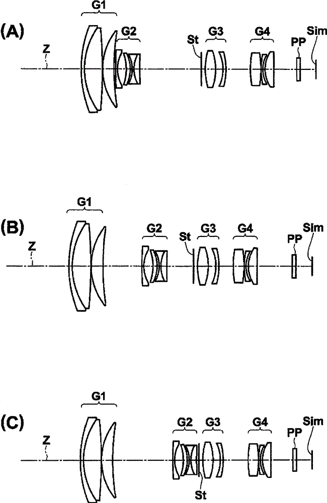
Embodiment 2
[0145] Example 2 Basic Lens Data
[0146]
[0147]
[0148] table 5
[0149] Embodiment 2 and data related to variable power
[0150]
wide angle end
middle
telephoto end
Variable 1
0.688
16.177
26.222
Variable 2
26.553
11.064
1.019
Variable 3
10.574
5.983
10.915
Variable 4
10.000
14.591
9.659
f
8.051
24.958
76.725
FNo.
1.67
1.99
2.22
2ω
58.43
18.45
5.88
[0151] Table 6
[0152] Embodiment 2 Aspherical data
[0153]
[0154] Table 7
Embodiment 3
[0155] Embodiment 3 basic lens data
[0156]
[0157]
[0158] Table 8
[0159] Embodiment 3 and data related to variable power
[0160]
wide angle end
middle
telephoto end
Variable 1
1.231
16.590
26.440
Variable 2
26.340
10.981
1.131
Variable 3
13.074
8.621
13.477
[0161] Variable 4
10.000
14.453
9.597
f
8.064
25.000
76.854
FNo.
1.67
1.99
2.22
2ω
58.43
18.45
5.88
[0162] Table 9
[0163] Embodiment 3 Aspherical data
[0164]
[0165] Table 10
PUM
 Abstract
Description
Claims
Application Information