Fuse mounting component

A technology for installing components and fuses, applied in the field of fuses, can solve the problems of fatigue fracture of internal components of fuses, limited degrees of freedom, fatigue fracture of fuse components, etc., to achieve the effects of not easy fatigue fracture, low cost, and simple manufacturing

Active Publication Date: 2015-01-21
YAZAKI CORP
View PDF6 Cites 0 Cited by
  • Summary
  • Abstract
  • Description
  • Claims
  • Application Information

AI Technical Summary

Problems solved by technology

[0008] In the fuse mounting part described in Patent Document 1, due to the difference in thermal expansion coefficient of each material of the fuse and the fuse mounting part, deformation caused by repeated expansion and contraction causes fatigue fracture to occur in the internal components of the fuse
[0009] If you want to avoid this situation, you should choose the fuse and fuse mounting parts with close thermal expansion rate when selecting materials, but this leads to the result of limited design freedom
However, since it is not easy to select components with exactly the same thermal expansion rate, there is still a problem that the deformation caused by the different thermal expansion rate of the material leads to fatigue fracture of the internal components of the fuse.

Method used


Image

  • Fuse mounting component
  • Fuse mounting component
  • Fuse mounting component

Examples


Embodiment Construction

[0020] Hereinafter, the fuse mounting member of the present invention that does not cause fatigue in the internal components of the fuse even if the thermal expansion coefficients of the fuse and the fuse mounting member are different will be described with reference to the drawings.

[0021]

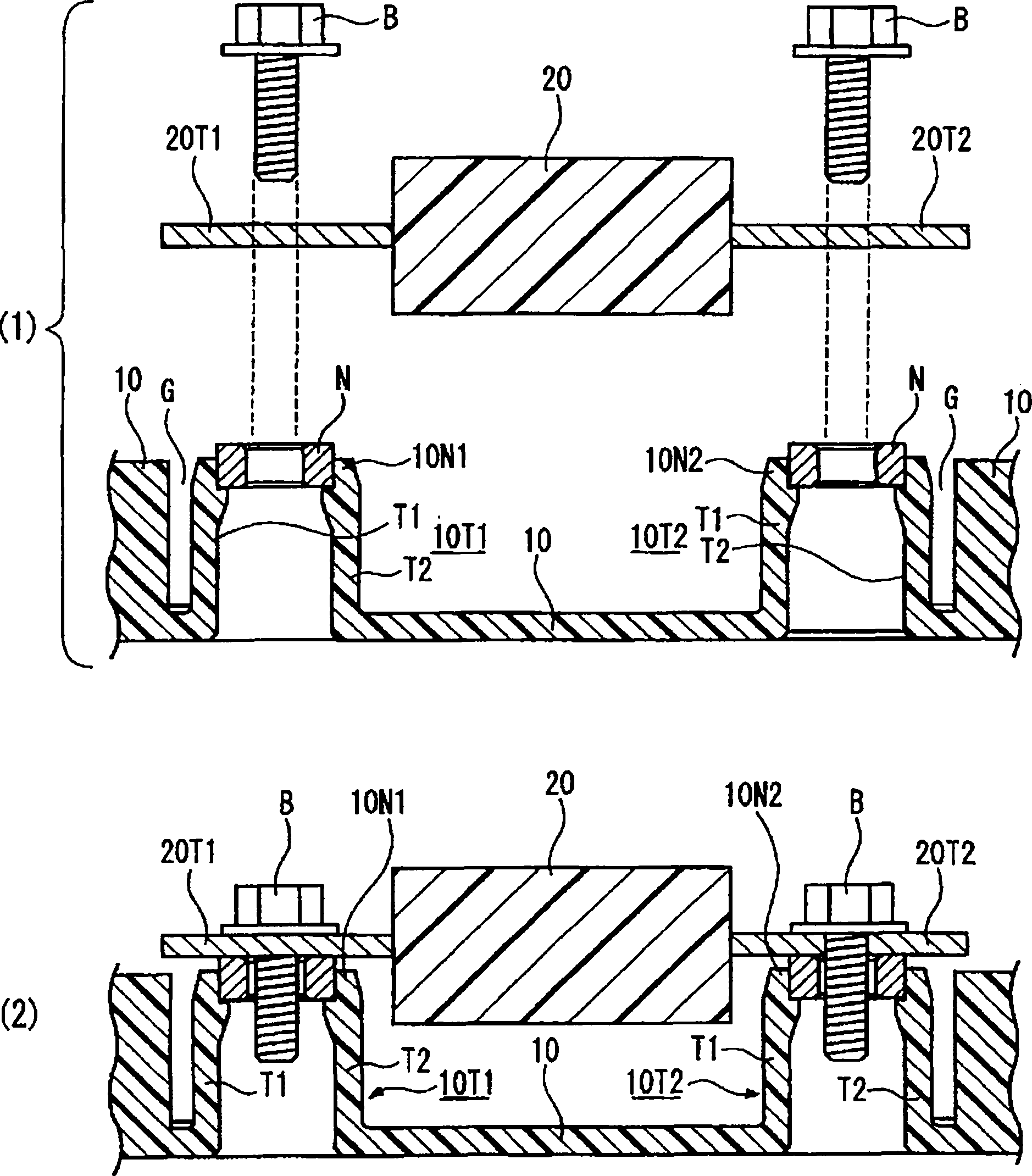
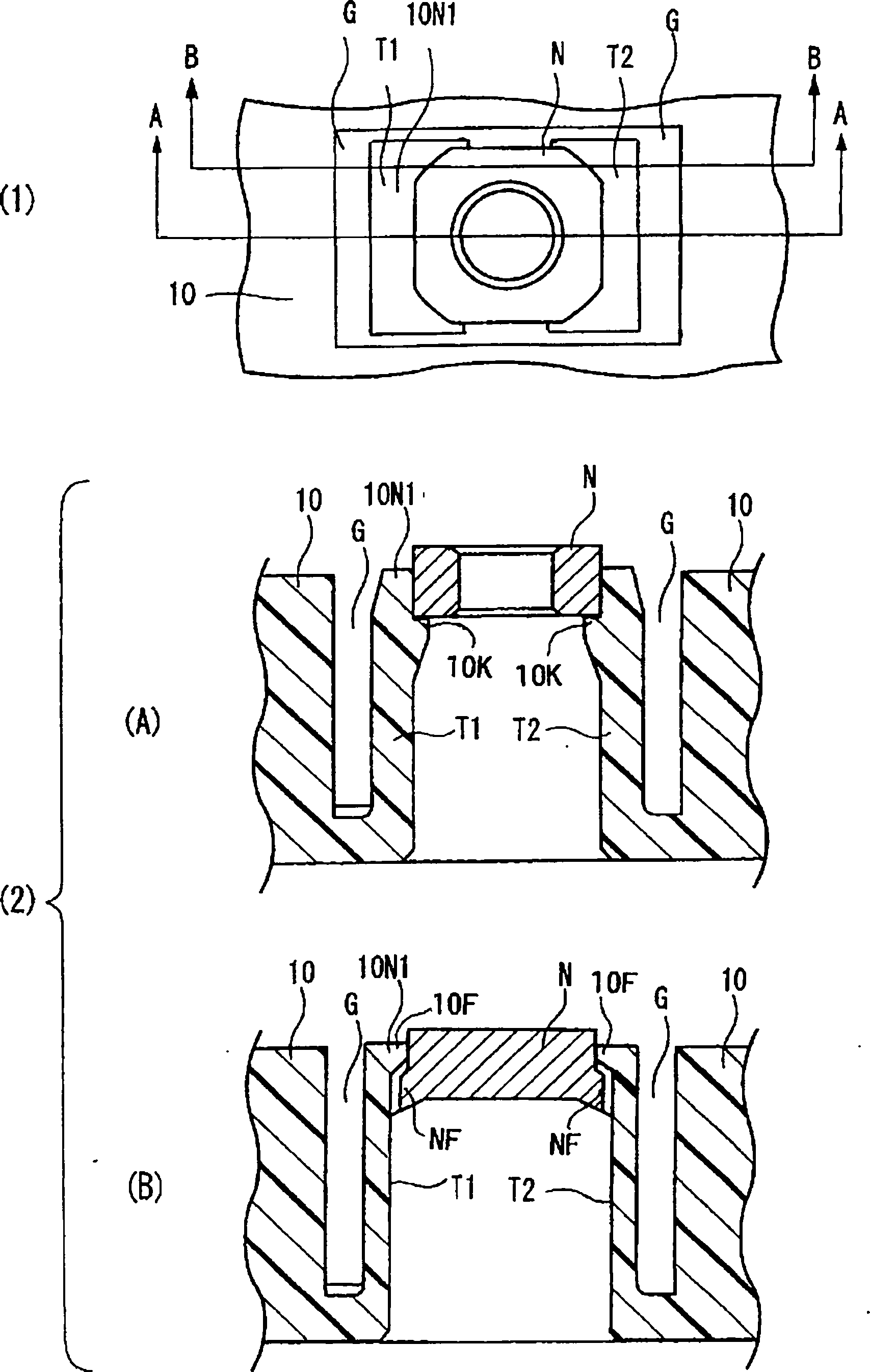
[0022] figure 1 and figure 2 It is a figure explaining the fuse mounting part which concerns on this invention. figure 1 It is a vertical cross-sectional view of the fuse installation part, wherein (1) shows the state before the fuse is installed; (2) shows the state after the fuse is installed. figure 2 yes means figure 1 The figure of the nut part of the fuse installation part of , wherein (1) is a top view; (2) is a longitudinal sectional view of the nut, wherein (A) is the A-A section of (1); (B) is the B-B of (1) section. exist figure 1 and figure 2 Among them, 10T1 and 10T2 are support portions of the present invention for fixing the nuts N, respectively. The suppo...


PUM


Abstract

PROBLEM TO BE SOLVED: To provide a fuse attachment component, preventing fatigue breakage of an internal element of a fuse caused by different thermal expansion coefficients between the fuse and the attachment component therefor.SOLUTION: Support portions 10T1 and 10T2 of a fuse attachment component 10 are respectively constituted by two stoppage arms T1 and T2. At each vertex of the stoppage arms T1 and T2, nut fixation portions 10N1 and 10N2 are provided. A space G is formed between the nut fixation portions 10N1 and 10N2 and the fuse attachment component 10. When both terminals 20T1 and 20T2 of a fuse 20 are fixed to nut fixation portions 10N1 and 10N2 by a nut N, the nut fixation portions 10N1 and 10N2 are displaced because of the existence of the formed space G, even if a load is to be imposed to the internal element of the fuse due to different thermal expansion coefficients between the fuse and the attachment component therefor. Thus, both terminals 20T1 and 20T2 of the fuse 20 are also displaced, so that no large stress is imposed to the internal element.

Description

technical field [0001] The present invention relates to a fuse for protecting electronic equipment from damage caused by short-circuit current or overcurrent from a storage battery used in an electric vehicle, and particularly relates to a fuse mounting part so that a fuse for mounting a fuse is mounted Parts are not easily damaged. Background technique [0002] <Fuse mounting part described in Patent Document 1> [0003] A fuse mounting part in which both terminals of a fuse are mounted to a nut provided on a resin molded part with set screws is known. (For example, refer to Patent Document 1). Figure 4 It is a figure explaining the conventional fuse mounting part of the invention described in patent document 1, (1) is a plan view; (2) is a vertical cross-sectional view. [0004] Figure 4 In this example, a nut N is fixed to a fuse mounting member 100 which is a resin molded part. Both terminals 20T of the fuse 20 are respectively fixed to the nut N by fixing scr...

Claims


Application Information

Patent Timeline
Patent Type & Authority Patents(China)
IPC IPC(8): H01H85/22
Inventor 池田智洋泷下隆太
Owner YAZAKI CORP
Why Eureka
Try Eureka