
A method and device for configuring dynamic subframes in a time division duplex system

A time-division duplex system and dynamic subframe technology, which is applied to the separation device of the transmission path, transmission system, signaling distribution, etc., can solve the problems that the base station side cannot be measured, the terminal side cannot be measured, and uplink resources are wasted, etc., so as to improve The effect of spectrum utilization

Active Publication Date: 2015-08-12
GUANGDONG OPPO MOBILE TELECOMM CORP LTD
View PDF4 Cites 0 Cited by
  • Summary
  • Abstract
  • Description
  • Claims
  • Application Information

AI Technical Summary

Problems solved by technology

For the first example, using the existing method, the current cell needs to set its own uplink subframe 4 and uplink subframe 9 as blank subframes to reduce the interference between itself and adjacent cells, but in this way, the uplink subframe 4 , Uplink subframe 9 cannot transmit sounding reference symbol (SRS, Sounding Reference Signal), physical uplink control channel (PUCCH, Physical Uplink Control Channel), physical uplink shared channel (PUSCH, Physical Uplink Shared Channel), resulting in the base station side can not measure , affecting the uplink ACK / NACK feedback, the downlink HARQ process, and causing serious waste of uplink resources, etc.; in the second example above, using the existing method, the current cell needs to set its own downlink subframe 4 and downlink subframe 9 It is a blank subframe to reduce interference between itself and adjacent cells, but in this way, downlink subframe 4 and downlink subframe 9 cannot transmit cell reference symbols (CRS, Cell-specific reference signals), physical downlink control channel (PDCCH , Physical downlink control channel), physical HARQ indicator channel (PHICH, Physical hybrid-ARQ indicator channel), physical downlink shared channel (PDSCH, Physical downlink shared channel), resulting in measurement failure on the terminal side, affecting downlink ACK / NACK feedback, uplink HARQ process, and lead to a serious waste of downlink resources

Method used


Image

  • A method and device for configuring dynamic subframes in a time division duplex system
  • A method and device for configuring dynamic subframes in a time division duplex system
  • A method and device for configuring dynamic subframes in a time division duplex system

Examples


example 1

[0050]In this embodiment, the TDD system includes 3 cells, which are cell 1 (Cell_1), cell 2 (Cell_2), and cell 3 (Cell_3), and the initial uplink and downlink subframe configurations of Cell_1, Cell_2, and Cell_3 all use the table The uplink and downlink subframe configuration 0 in 1, after that, Cell_2 switches to uplink and downlink subframe configuration 1 due to more downlink traffic, and Cell_3 also switches to uplink and downlink subframe configuration 2 because of more downlink traffic than Cell_2, However, Cell_1 still adopts uplink and downlink subframe configuration 0.

[0051] In this embodiment, according to Table 1, after switching, such as Figure 4 as shown, Indicates that subframes #3 and #8 of Cell_1 and Cell_2 are still uplink subframes, Indicates that the subframes #3 and #8 of Cell_3 are converted into downlink subframes. In this way, interference will occur between Cell_1 and Cell_3, and between Cell_2 and Cell_3 on subframes #3 and #8. In order to el...

example 2

[0058] In this embodiment, the initial uplink and downlink subframe configurations of Cell_1, Cell_2, and Cell_3 in the TDD system are configured as the uplink and downlink subframe configuration 2 in Table 1. Afterwards, due to the increase of uplink services in Cell_2, the uplink and downlink subframe configuration of Cell_2 Switched to uplink and downlink subframe configuration 1 in Table 1. Since the uplink traffic in Cell_3 has increased more, the uplink and downlink subframe configuration of Cell_3 will be switched to uplink and downlink subframe configuration 0 in Table 1, while Cell_1 still uses uplink and downlink subframe configuration Subframe configuration 2.

[0059] After switching, as in Figure 5 as shown, Indicates that subframes #3 and #8 of Cell_1 are still downlink subframes, Indicates that the subframes #3 and #8 of Cell_2 and Cell_3 are converted into uplink subframes, so that interference will occur between Cell_1 and Cell_2, and between Cell_1 and C...

example 3

[0064] For the scenario of the second embodiment above, the method of this embodiment may also be used to reduce the interference between the three cells Cell_1, Cell_2, and Cell_3 due to different configurations of uplink and downlink subframes.

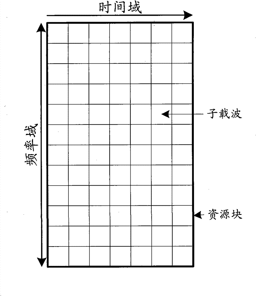
[0065] For the interference existing on subframes #3 and #8, the following methods can be used: Figure 6 , Figure 7 , Figure 8 The three methods shown eliminate, specifically:

[0066] Such as Figure 6 As shown, on Cell_3 subframes #3 and #8, the resources other than the control domain in the first time slot in the set bandwidth and the resources in the second time slot in the set bandwidth are silenced, as shown in Figure 6 middle corresponding resources And, mute some resources in Cell_1 and Cell_2 subframes #3 and #8 corresponding to the unmuted resources in the Cell_3 subframes #3 and #8, as Figure 6 middle corresponding resources and resources in, Indicates the mute resource corresponding to the unmuted co...


PUM


Abstract

The present application discloses a dynamic sub-frame configuration method in the TDD system. The method includes: in the case that the uplink and downlink sub-frame configuration of a cell and the uplink and downlink sub-frame configuration of its neighboring cell are different in the configuration of a sub-frame, a part of resources on the sub-frame are made to be silent for the cell, and the resources on the sub-frame corresponding to the resources not silenced on the sub-frame for cell are made to be silent for the neighboring cell; or, a part of resources on the sub-frame are made to be silent for the neighboring cell, and the resources on the sub-frame corresponding to the resources not silenced on the sub-frame for the neighboring cell are made to be silent for the cell. The present application further provides a dynamic sub-frame configuration apparatus in the TDD system. Not only can the problem that inter-cell interference is introduced during sub-frame switching in the TDD system be solved, but also the normal uplink and downlink measurement can be guaranteed, without affecting ACK / NACK feedback and HARQ process, and meantime the frequency spectrum utilization ratio is increased.

Description

technical field [0001] The present invention relates to the time division duplex (TDD, Time Division Duplex) system of Long Term Evolution (LTE, Long Term Evolution) and Advanced Long Term Evolution (LTE-A, Long Term Evolution Advanced) in the third generation partnership project (3GPP), especially relates to A method and device for configuring dynamic subframes in a TDD system. Background technique [0002] Duplex technology is an important part of the mobile communication system, and it is also a symbolic technology of the mobile communication system. On the basis of meeting the transmission needs, it realizes the isolation of uplink and downlink resources at the same time, ensures the normal transmission, and effectively reduces mutual interference. interference. The duplex technology used in the mobile communication system mainly includes Frequency Division Duplex (FDD, Frequency Division Duplex) and TDD. Among them, FDD operation requires two independent frequency ban...

Claims


Application Information

Patent Timeline
Patent Type & Authority Patents(China)
IPC IPC(8): H04W28/16H04B7/26H04L27/26
CPCH04L5/0053H04L5/0044H04L5/0003H04W16/10H04L27/2601H04W72/0446H04L5/1469H04L5/0073
Inventor 胡留军毕峰朱常青
Owner GUANGDONG OPPO MOBILE TELECOMM CORP LTD
Learn More