Adaptive beam position parameter optimization method for synthetic aperture radar satellite and system

A synthetic aperture radar, self-adaptive technology, applied in radio wave measurement system, radio wave reflection/reradiation, utilization of reradiation, etc., can solve the problem of high computational complexity, can not meet the requirements of wave position design, does not take into account Design Difficulty etc.

Inactive Publication Date: 2013-03-20
BEIHANG UNIV
View PDF3 Cites 0 Cited by
  • Summary
  • Abstract
  • Description
  • Claims
  • Application Information

AI Technical Summary

Problems solved by technology

However, this method also has some shortcomings, including: firstly, due to the irregularity of the pulse optional area, when designing the next wave position from the current wave position, it is often necessary to continuously adjust parameters such as the overlap rate, and the calculation complexity is high, which leads to the design algorithm The efficiency is low; secondly, although the wave position parameter set designed by the algorithm can meet the coverage requirements, it is not rich enough to meet the wave position design requirements of the new working mode of high-resolution spaceborne SAR; in addition, the algorithm does not have Considering the difficulty of wave position design under large viewing angles, it is difficult to meet the requirements of the wave position performance indicators, especially the azimuth ambiguity and equivalent noise coefficient under the large viewing angle, and it is necessary to properly correct the wave position parameters

Method used


Image

  • Adaptive beam position parameter optimization method for synthetic aperture radar satellite and system
  • Adaptive beam position parameter optimization method for synthetic aperture radar satellite and system
  • Adaptive beam position parameter optimization method for synthetic aperture radar satellite and system

Examples


Embodiment

[0183] SAR performance index parameters, satellite orbit parameters and SAR system parameters are shown in Table 1, Table 2 and Table 3

[0184] Table 1 SAR performance index parameters

[0185]

[0186] Table 2 Satellite orbit parameters

[0187]

[0188]

[0189] Table 3 SAR system parameters

[0190]

[0191] Select time t=0, and carry out adaptive wave position design according to the parameters in Table 1, Table 2 and Table 3.

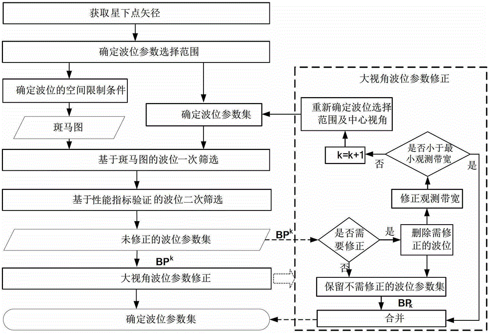
[0192] Step 1: Obtain satellite altitude and sub-satellite point vector;

[0193] Calculated by formulas (1)~(5), the average pericentric angle of the satellite at time t=0 is M=0, the true pericentric angle θ=0, the polar radius r=6919110m, and the length of the geocentric vector corresponding to the sub-satellite point R e =6378137m, track height H=540973m.

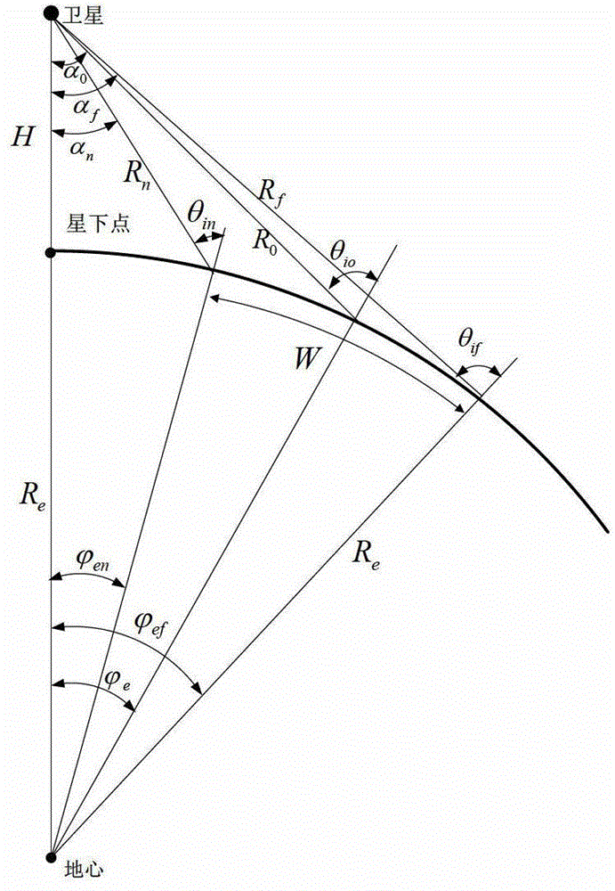
[0194] After obtaining the altitude of the satellite orbit and the vector radius of the sub-satellite point, determine the geometric relationship between the satellite and ...


PUM


Abstract

The present invention discloses an adaptive beam position design method for a synthetic aperture radar satellite and a system. The method includes the following steps: obtaining the orbit altitude and the substellar point radius vector of a satellite; determining the selection range of beam position parameters; determining the space restrictions for the beam position; designing a beam position parameter set; sifting beam position parameters for the first time based on the zebra diagram; sifting beam position parameters for the second time based on SAR property indices; and correcting beam position parameters by a large viewing angle. The system comprises an obtaining module for the orbit altitude and the substellar point radius vector of the satellite, a determining module for the selection range of the beam position, a determining module for the space restrictions for the beam position, a design module for beam position parameter set, a beam position parameter sifting module based on the zebra diagram, a beam position parameter sifting module based on the SAR property indices, and a beam position parameter correcting module with a large viewing angle. The present invention achieves high-beam-position parameter correction for the difficulties of beam position design with a large viewing angle, and the beam position design method proposed by the present invention integrates property index calculation and has the characteristic of beam position design integration.

Description

technical field [0001] The invention relates to a synthetic aperture radar (SAR) satellite adaptive wave position parameter optimization method and system, belonging to the technical field of radar system design. Background technique [0002] Spaceborne synthetic aperture radar has all-weather and all-weather working capabilities, and it is an earth observation system that has attracted much attention at present. Beam position, short for beam position, refers to the beam pointing of the radar, and the wave position parameters include beam pointing and pulse repetition frequency. Spaceborne SAR observes the earth according to the wave position parameters, obtains echo data and then forms an image. Therefore, the selection of wave position parameters directly determines the working state of spaceborne SAR, and closely affects the quality of SAR images and system performance. In addition, choosing an appropriate wave position parameter can effectively shorten the revisit peri...

Claims


Application Information

Patent Timeline
Patent Type & Authority Patents(China)
IPC IPC(8): G01S7/41G01S13/90
Inventor 王志乾于泽李春升
Owner BEIHANG UNIV
Why Eureka
Try Eureka