Optical fiber electric heat tape

A technology of electric heating belt and optical fiber, which is applied in the direction of measuring heat, heating element shape, measuring device, etc., can solve the problem of difficulty in accurately determining the fault point of electric heating belt, and achieve the effect of facilitating maintenance and ensuring safe transportation.

Inactive Publication Date: 2012-03-28
大庆航天三沃新技术产业有限责任公司
View PDF6 Cites 4 Cited by
  • Summary
  • Abstract
  • Description
  • Claims
  • Application Information

AI Technical Summary

Problems solved by technology

[0004] The purpose of the present invention is to provide an optical fiber electric heating cable to solve the problem that it is difficult to accurately determine the fault point of a long electric heating cable

Method used


Image

  • Optical fiber electric heat tape
  • Optical fiber electric heat tape
  • Optical fiber electric heat tape

Examples


specific Embodiment approach 1

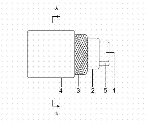
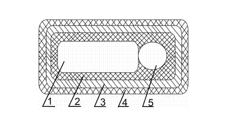
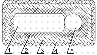
[0007] Specific implementation mode one : combined below figure 1 and figure 2 This embodiment will be specifically described. This embodiment includes an electric heating belt body 1, which also includes an optical fiber 5, an inner sheath 2, a shielding layer 3 and an outer sheath 4. Rely, the inner sheath 2, the shielding layer 3 and the outer sheath 4 are wrapped sequentially from the inside to the outside on the heating belt body 1 and the outer wall of the optical fiber 5.

specific Embodiment approach 2

[0008] Specific implementation mode two : combined below figure 1 and figure 2 This embodiment will be specifically described. The difference between this embodiment and the first embodiment is that the heating belt body 1 is a series heating belt or a parallel heating belt.

specific Embodiment approach 3

[0009] Specific implementation mode three : combined below figure 1 and figure 2 This embodiment will be specifically described. The difference between this embodiment and the first embodiment is that the heating belt body 1 is a constant temperature heating belt or a self-limiting temperature heating belt.


PUM


Abstract

The invention provides an optical fiber electric heat tape and relates to an electric heat tape, and the optical fiber electric heat tape can be used for solving the problem that the fault point of a very long electric heat tape is difficult to accurately judge. The optical fiber electric heat tape comprises an electric heat tap body, an optical fiber (5), an inner sheath (2), a shielding layer (3) and an outer sheath (4), wherein the optical fiber (5) is arranged along the length direction of the electric heat tape body (1) and props against the electric heat tape body (1); the inner sheath (2), the shielding layer (3) and the outer sheath (4) are sequentially coated on the outer walls of the electric heat tape body (1) and the optical fiber (5) from inside to outside; once a certain point on the electric heat tape has a fault, the optical fiber can monitor the temperature change of the point in real time, and the change of reflected signal receiving time can accurately report the position of the fault point, so that maintenance can be organized quickly and conveniently, and the electric heat tape is restored to normal operation within minimum duration. The optical fiber electric heat tape can be used for heating conveying pipelines and storage tanks in the industries of buildings, steel, power and the like.

Description

[0001] technical field [0002] The invention relates to an electric heating belt. Background technique [0003] According to its structure, electric heating belt can be divided into two types: series connection and parallel connection, and according to its performance, it can be divided into two types: constant power and self-limiting temperature. Electric heating belts are being used more and more widely in the industrial field, and are widely used in the fields of heat preservation, anti-coagulation, and anti-freezing of pipelines and storage tanks in construction, steel, and electric power industries; especially in oil storage tanks and storage tanks in the petrochemical industry. On long-distance pipelines, electric heating belts have obvious advantages. Its shortcoming is that the length of the electric heating belt depends on the length of the heated body, and sometimes the distance is very long. Once a fault occurs at a certain point, it is difficult to accurately d...

Claims


Application Information

Patent Timeline
Patent Type & Authority Applications(China)
IPC IPC(8): H05B3/56G01K11/32
Inventor 杜建芳宋彬王海峰
Owner 大庆航天三沃新技术产业有限责任公司
Why Eureka
Try Eureka