Cooling system for battery systems and a method for cooling battery systems

A technology of cooling system and battery system, applied in the field of cooling system

Active Publication Date: 2012-03-28
LG ENERGY SOLUTION LTD
View PDF3 Cites 13 Cited by
  • Summary
  • Abstract
  • Description
  • Claims
  • Application Information

AI Technical Summary

Problems solved by technology

However, typical air-cooled battery packs present significant challenges in maintaining the temperature of the pack within the desired temperature range

Method used


Image

  • Cooling system for battery systems and a method for cooling battery systems
  • Cooling system for battery systems and a method for cooling battery systems
  • Cooling system for battery systems and a method for cooling battery systems

Examples


Embodiment Construction

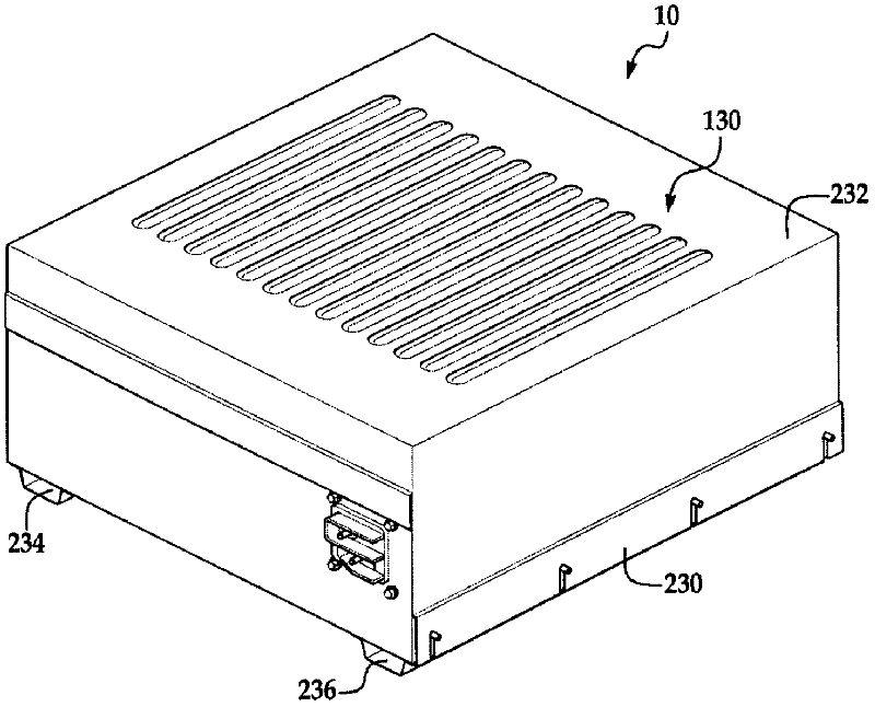
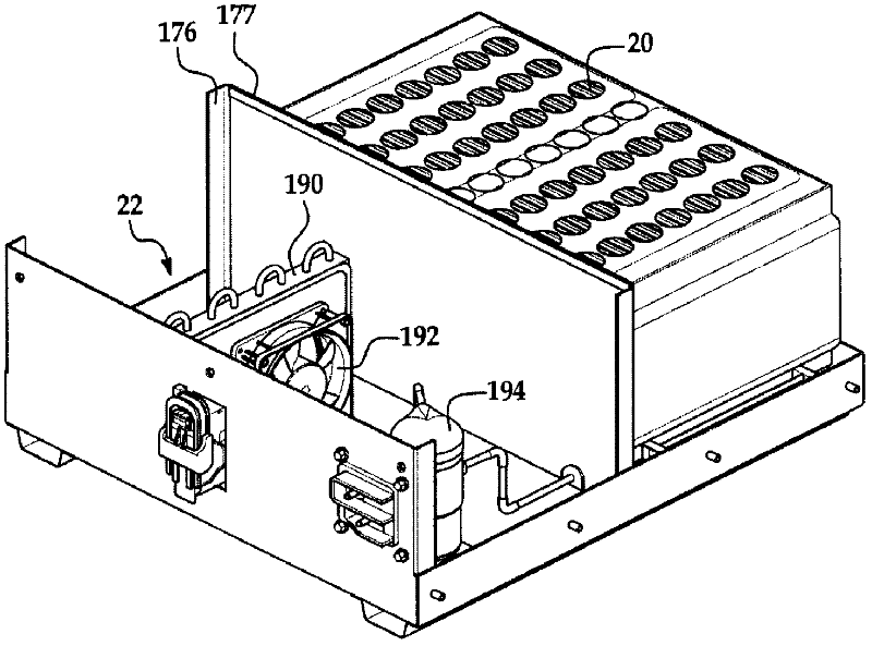
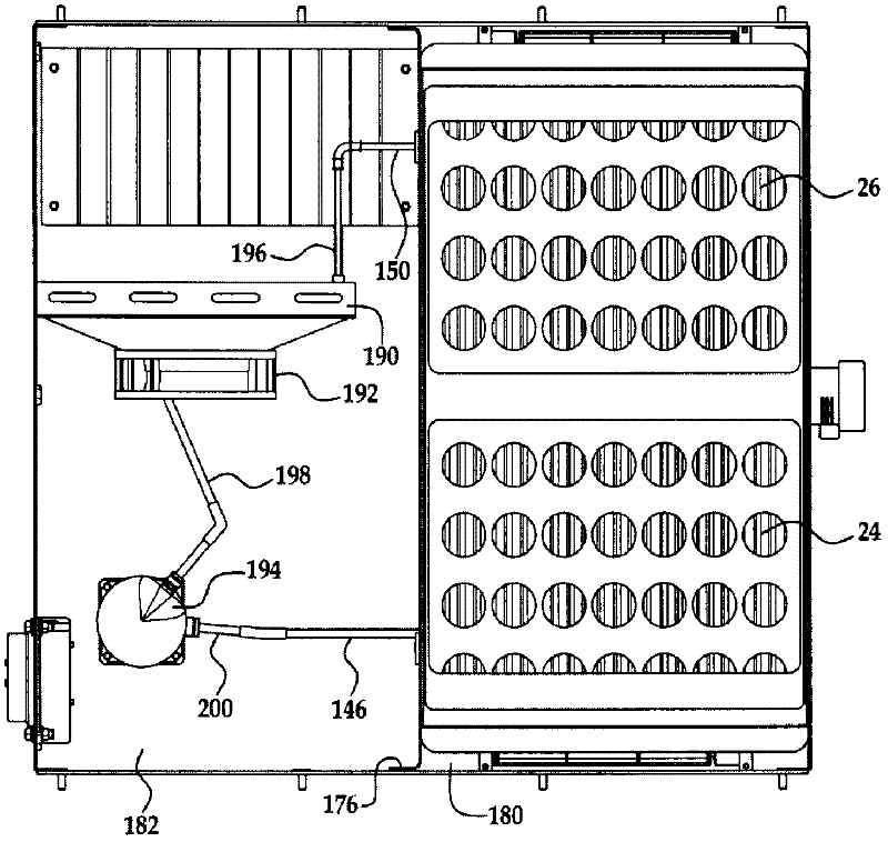
[0020] refer to Figure 1-3 , shows a power generation system 10 for outputting electric power according to an exemplary embodiment. Power generation system 10 includes battery system 20 and cooling system 22 .

[0021] The battery system 20 is configured to output electric power. The battery system 20 includes battery modules 24 , 26 . Each of the battery modules 24, 26 has a similar structure and includes a plurality of battery cell assemblies that can be electrically connected to each other in series or in parallel. For purposes of brevity, only a portion of the battery cell assemblies in battery module 24 will be described in detail. For example, refer to Figure 8-10 , the battery module 24 includes battery cell assemblies 28, 29, 30, 31, 32, 33, 34, 36, 38, 40, and 42 and flow channel manifolds 60, 62, 64, 66, 68, 70, 72, 74, 76 and 78. Each of the battery cell assemblies has a battery cell therein that generates an operating voltage between a pair of electrodes ex...


PUM


Abstract

The present invention provides a cooling system for battery systems and a method for cooling battery systems. The cooling system comprises: a housing which has a first enclosed portion and a second enclosed portion, and a first evaporator which recirculates air in a first closed flow-pathway loop within a first hermetically sealed part and is positioned within the first enclosed portion. The first evaporator extracts heat energy from the air in the first closed flow-pathway loop and so lowers the temperature level of a first battery module within the first enclosed portion. The cooling system comprises a condenser which is positioned within the second enclosed portion and fluidly connected to the first evaporator, and which receives the heat energy in a coolant from the first evaporator and disperses the heat energy.; The cooling system also comprises a compressor which is positioned within the second enclosed portion, and recirculates the coolant through the first evaporator and the condenser.

Description

technical field [0001] The present application relates to a cooling system for a battery system and a method for cooling a battery system. Background technique [0002] In a typical air-cooled battery pack, ambient air from the ambient atmosphere is directed through the battery cells in the pack and then exhausted from the pack. However, typical air-cooled battery packs present significant challenges in maintaining the temperature of the battery pack within a desired temperature range. [0003] In particular, the maximum operating temperature of a battery cell can often be less than the temperature of the ambient air used to cool the battery. In this case, it is impossible to maintain the battery cells within the desired temperature range in an air-cooled battery pack. [0004] Accordingly, the inventors herein have recognized a need for an improved battery cell assembly that minimizes and / or eliminates the above-mentioned disadvantages. Contents of the invention [000...

Claims


Application Information

Patent Timeline
Patent Type & Authority Applications(China)
IPC IPC(8): H01M10/50H01M10/48H01M2/20H01M2/10F25D17/00H01M50/209
CPCF25D2700/16H01M10/5079H01M2/10H01M2/20H01M10/50Y02E60/12H01M10/5022H01M10/48H01M2/1016F25D2317/0682H01M10/5004F25D29/00F25D17/00H01M10/5067H01M10/486H01M10/633H01M10/6563H01M10/6569H01M10/613Y02E60/10H01M50/209
Inventor 威廉姆·克廷乔斯·佩恩夸克·汤姆
Owner LG ENERGY SOLUTION LTD
Why Eureka
Try Eureka