Fuel Cell System

Inactive Publication Date: 2014-10-16
DAIMLER AG
View PDF2 Cites 3 Cited by
  • Summary
  • Abstract
  • Description
  • Claims
  • Application Information

AI Technical Summary

Benefits of technology

The present invention is about a fuel cell system that prevents freezing of important components without using energy-intensive heating. The system includes a condensation unit that intentionally creates a region where water vapor can condense and freeze. This prevents damage to the fuel cell system and ensures reliable operation even under adverse conditions. The condensation unit has built-in components that enlarge the inner surface, which provides a large surface area for the condensation of water vapor. This results in secure and reliable prevention of freezing of necessary flow cross sections with a small installation size of the condensation unit.

Problems solved by technology

The problem is that this liquid water may freeze at ambient temperatures below the freezing point.
Functionally relevant components, in particular line cross sections, gas channels, and the like thus become clogged with ice, so that restarting the fuel cell system is impossible, or possible only with a significant expenditure of energy and considerable loss of time.
The procedure of heating critical components during switching-off of the fuel cell system has the significant drawback that it is comparatively energy-intensive.
In addition, the heating of the fuel cell may very easily result in damage to the membranes, thus disadvantageously reducing the service life of a fuel cell.
Instead of the undirected condensation of water at an arbitrary location within the fuel cell system that cannot be influenced, this results in targeted condensation in the region of the condensation unit.

Method used


Image

  • Fuel Cell System
  • Fuel Cell System
  • Fuel Cell System

Examples


Embodiment Construction

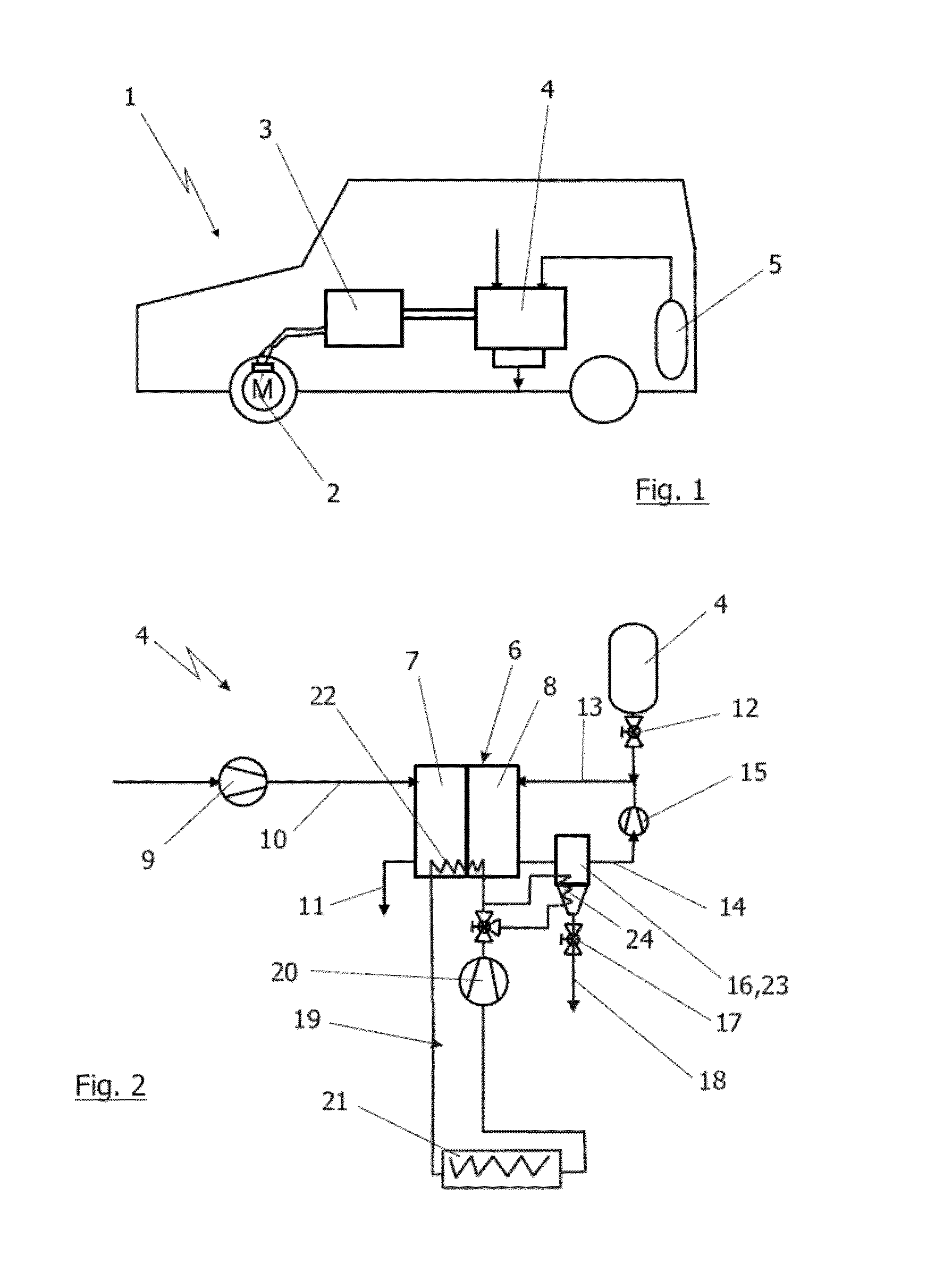
[0016]The illustration in FIG. 1 shows a vehicle 1. This schematically indicated vehicle 1 is designed to be driven via an electric motor 2 by way of example, which is indicated in the region of the wheels, and which via a power electronics system 3 is supplied with electrical power from a fuel cell of a fuel cell system 4 indicated overall by a box. In addition, an energy store in the form of a battery, for example (not illustrated), may be present which is likewise controlled via the power electronics system 3 and which in particular may be used for accepting and delivering regenerated braking energy. Air and hydrogen are supplied to the fuel cell system 4 in a known manner for generating the required electrical power. The hydrogen originates from one or more compressed gas stores 5, optionally distributed over the vehicle 1, of which one compressed gas store is illustrated here by way of example. The fuel cell system 4 is described in greater detail in the illustration in FIG. 2....


PUM


Abstract

A fuel cell system includes at least one fuel cell, line elements for supplying and discharging starting materials and / or products to / from the fuel cell, and at least one condensation unit. The condensation unit is situated in at least one of the line elements and, at least in individual operating phases of the fuel cell, the condensation unit is at a lower temperature level than the areas surrounding it and the fuel cell.

Description

BACKGROUND AND SUMMARY OF THE INVENTION[0001]Exemplary embodiments of the invention relate to a fuel cell system.[0002]Fuel cell systems are known from the general prior art. They are typically used to provide electrical power from supplied starting materials such as hydrogen and oxygen. Such fuel cells are frequently designed as so-called PEM fuel cells, and have a membrane separating a cathode chamber that is supplied with oxygen from an anode chamber that is supplied with hydrogen. During operation, in addition to the electrical power, product water that is partly in gaseous form and partly in liquid form results, which is discharged from the fuel cell via the exhaust gases. In particular, when a so-called PEM fuel cell is used, it is also known and customary to appropriately humidify the starting materials supplied to the fuel cell, or at least one of the starting materials, typically the oxygen or the air that is used as the oxygen supplier. Thus, during operation, gases loaded...

Claims


Application Information

Patent Timeline
IPC IPC(8): H01M8/04
CPCH01M8/04164H01M8/04029H01M8/04067H01M8/04253Y02E60/50
Inventor BAUR, THOMASJESSE, MATTHIASLOHRI, CYRILLMAZZOTTA, COSIMORICHTER, HOLGERSCHERRBACHER, KLAUSSCHICK, CHRISTIAN
Owner DAIMLER AG
Why Eureka
Try Eureka