Water pump for pumping coolant in a low temperature and in a high temperature circuit

a high temperature circuit and water pump technology, applied in the direction of engine cooling apparatus, motors, leakage prevention, etc., can solve the problem of unsatisfactory heat transfer between the two cooling circuits

Inactive Publication Date: 2013-03-26
MOTOREN UND TURBINEN UNION MUNCHEN GMBH
View PDF7 Cites 3 Cited by
  • Summary
  • Abstract
  • Description
  • Claims
  • Application Information

AI Technical Summary

Benefits of technology

[0005]In a water pump for pumping coolant in a low temperature and a high temperature circuit with low temperature and high temperature housings each including a spiral flow guide structure, and a single rotor disposed in the joined housings and having a low temperature rotor part for pumping coolant through the low temperature circuit and a high temperature rotor part for pumping coolant through the high temperature circuit, the housings are joined with a heat isolating structure disposed between the flow guide structures of the high temperature and the low temperature housings to limit heat transfer from the high temperature coolant pumped through the high temperature housing to the low temperature coolant pumped through the low temperature housing.
[0008]It has been determined in test measurements that, with the measures according to the present invention, the heat flow from the high temperature to the low temperature circuit could be reduced by up to 70%. Since, as a result, less heat energy reaches the low temperature circuit, either the cooling system may be made smaller, lighter and less costly or the temperature level in the low-temperature circuit may be kept at a lower level which is advantageous for example for the cooling of electronic components.

Problems solved by technology

It is noted however that, with the good heat conductivity of the aluminum and the temperature difference between the high temperature and the low temperature circuit of for example 40° C., an undesirable heat transfer occurs between the two cooling circuits.

Method used


Image

  • Water pump for pumping coolant in a low temperature and in a high temperature circuit
  • Water pump for pumping coolant in a low temperature and in a high temperature circuit
  • Water pump for pumping coolant in a low temperature and in a high temperature circuit

Examples


Embodiment Construction

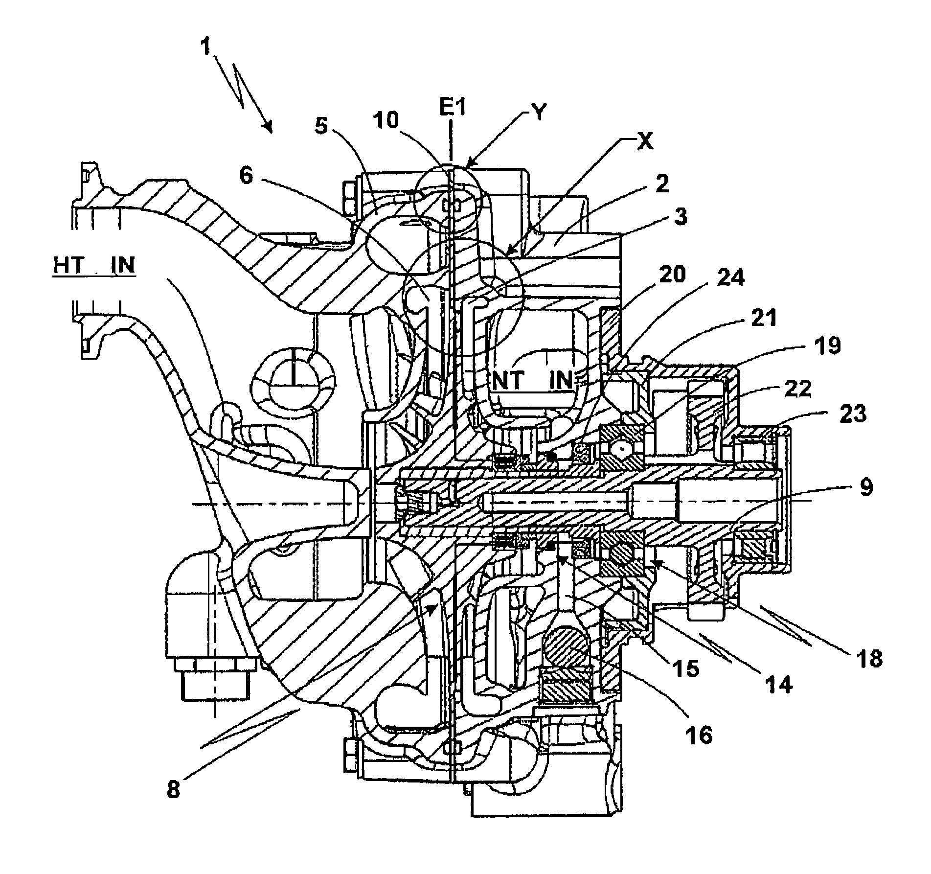
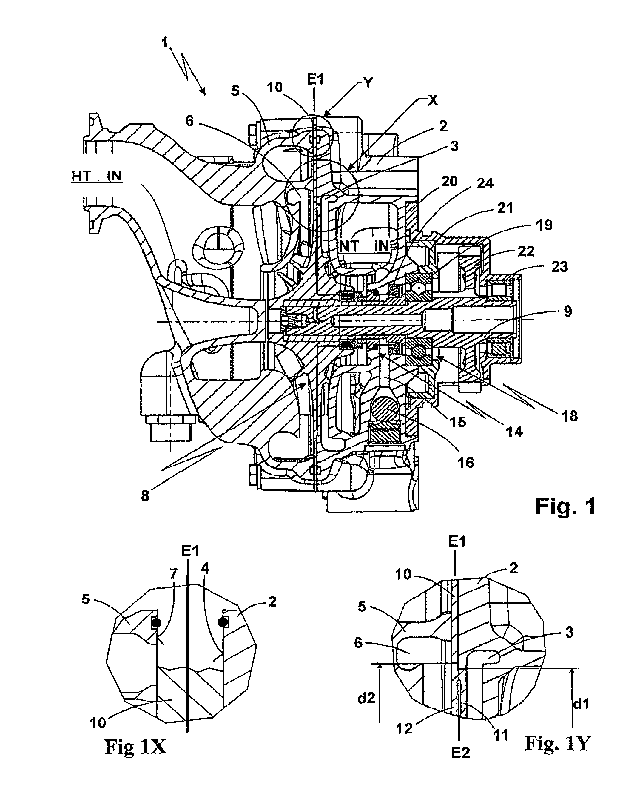
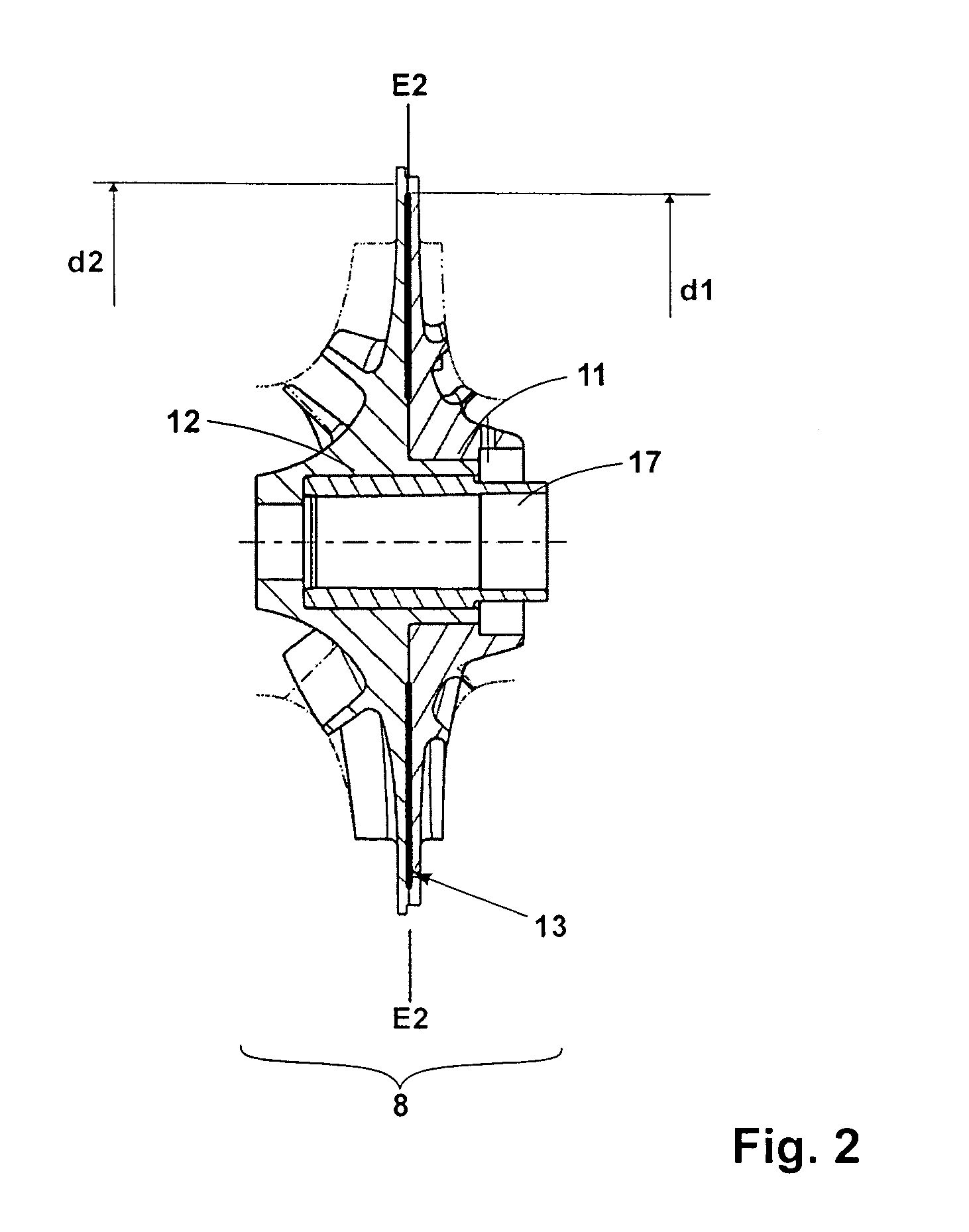
[0014]FIG. 1 shows a water pump 1 with details X and Y all shown in sectional views. The detail X (FIG. 1X) shows enlarged an area of the water pump rotor. The detail Y (FIG. 1Y) shows enlarged the connecting area of the pump housings at the outer circumference of the water pump. FIG. 2 shows the water pump rotor in a sectional view. The following description is provided referring to all the figures, FIG. 1, FIG. 1x, FIG. 1Y and FIG. 2.

[0015]The water pump as shown in FIG. 1 pumps coolant in a low temperature cooling circuit and, at the same time, coolant in a high-temperature circuit. The water pump 1 comprises the following main design groups: a low temperature housing 2, a high-temperature housing 5, a water pump rotor 8 for pumping the coolant, a drive shaft 9 for driving the water pump rotor 8 and a first bearing housing 20. In the low temperature housing 2, a low temperature spiral passage 3 is provided. The inlet of the low temperature coolant housing is designated in FIG. 1 ...


PUM


Abstract

In a water pump for pumping coolant in a low temperature and a high temperature circuit with low temperature and high temperature housings each including a spiral flow guide structure, and a single rotor disposed in the joined housings and having a low temperature rotor part for pumping coolant through the low temperature circuit and a high temperature rotor part for pumping coolant through the high temperature circuit, the housings are joined with a heat isolating structure disposed between the flow guide structures of the high temperature and the low temperature housings to limit heat transfer from the high temperature coolant pumped through the high temperature housing to the low temperature coolant pumped through the low temperature housing.

Description

BACKGROUND OF THE INVENTION[0001]The invention resides in a water pump for pumping coolant in a low temperature and in a high temperature circuit including a low temperature housing with an internal low temperature housing, a high temperature housing with an internal high temperature spiral, a water pump impeller for pumping at the same time coolant in the low temperature housing spiral and in the high temperature housing spiral, and a drive shaft for driving the water pump impeller.[0002]DE 41 14 704 C1 discloses a cooling circuit for two-stage charge air cooling. The cooling circuit comprises, a high-temperature and a low-temperature circuit. In the high temperature circuit, in series, a high temperature heat exchanger, a high temperature charge air cooler provided as a first cooling stage, a water pump for circulating coolant in the high-temperature circuit and the internal combustion engine are arranged. In the low temperature circuit, in series, a low-temperature heat exchanger...

Claims


Application Information

Patent Timeline
Patent Type & Authority Patents(United States)
IPC IPC(8): F04D1/00F04D29/22F04D29/58
CPCF04D29/5893F04D13/14F04D29/2211F04D1/006F01P7/165F01P2005/105F01P5/10F04D29/18F04D29/40
Inventor HARTMANN, MICHAELSULZMANN, MANFRED
Owner MOTOREN UND TURBINEN UNION MUNCHEN GMBH
Why Eureka
Try Eureka