Brushless motor control circuit assembly for ceiling fan

a technology of motor control circuit and ceiling fan, which is applied in the direction of motor/generator/converter stopper, dynamo-electric converter control, stopping arrangement, etc., can solve the problems of high noise level, waste of electricity, and release of heat, so as to reduce the temperature level of the brushless motor and save power consumption , accurate operation control

Inactive Publication Date: 2009-07-07
LEE HSIEN MENG +1
View PDF12 Cites 3 Cited by
  • Summary
  • Abstract
  • Description
  • Claims
  • Application Information

AI Technical Summary

Benefits of technology

[0006]The present invention has been accomplished under the circumstances in view. It is therefore the main object of the present invention to provide a brushless motor control circuit assembly, which saves much power consumption, and lowers the temperature level of the brushless motor.
[0007]To achieve these and other objects of the present invention, the brushless motor control circuit assembly is comprised of a power supply circuit, a booster and compensation circuit, a voltage regulator circuit, a microprocessor, a back electromagnetic force sensor, three driver circuits, and three output circuits. By means of detecting back electromagnetic force, the magnetic pole position of the brushless motor is known accurately, ensuring accurate operation control. By means of providing a high voltage to drive the drive circuits, the field effect transistors of the output circuits are operated under full conduction, saving much power consumption and lowering the working temperature of the brushless motor.

Problems solved by technology

The voltage of the field effect transistor is relatively low, and therefore the field effect transistor is not in “full conduction” for full power mode, i.e., the power factor is at a low level, wasting much electricity and releasing much heat.
However, this control method cannot eliminate vibration of the fan blade during rotation, resulting in a high noise level.

Method used


Image

  • Brushless motor control circuit assembly for ceiling fan
  • Brushless motor control circuit assembly for ceiling fan
  • Brushless motor control circuit assembly for ceiling fan

Examples


Embodiment Construction

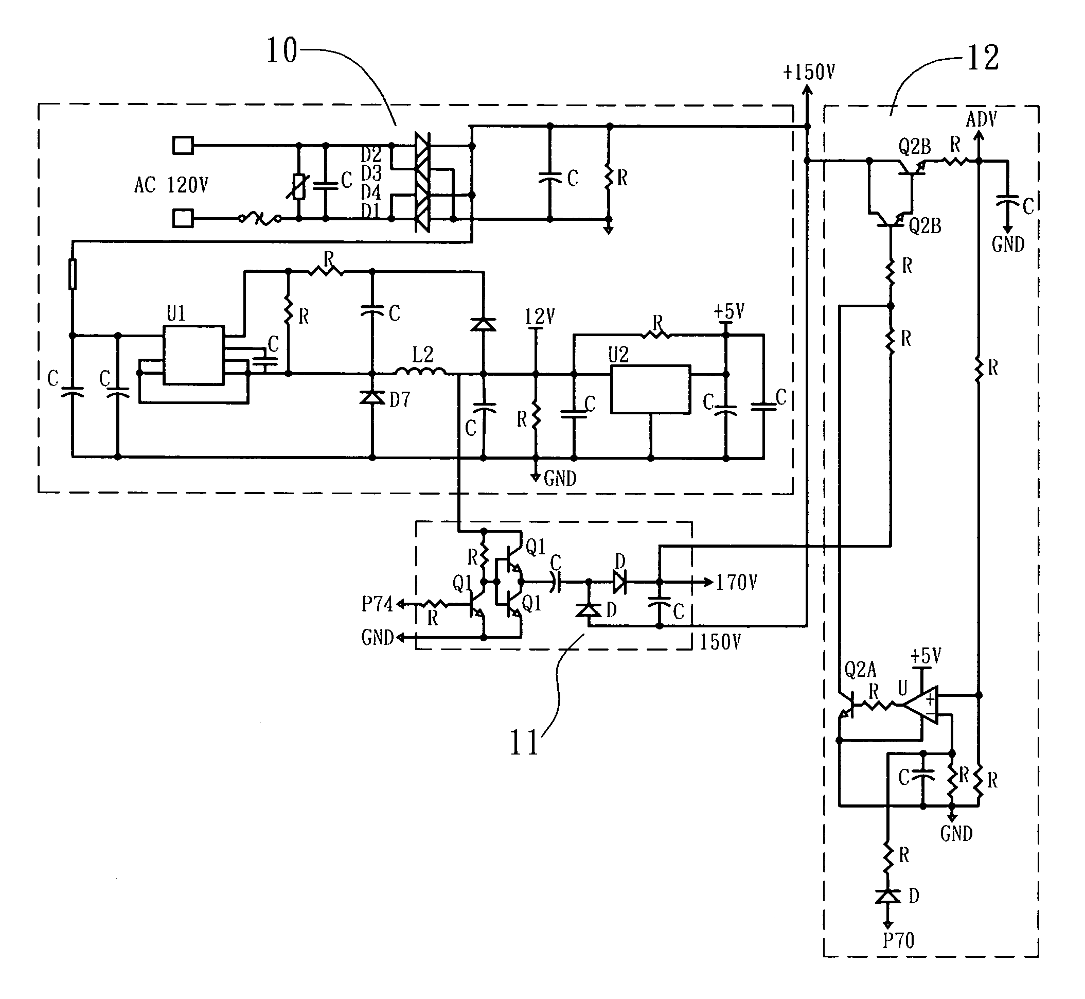
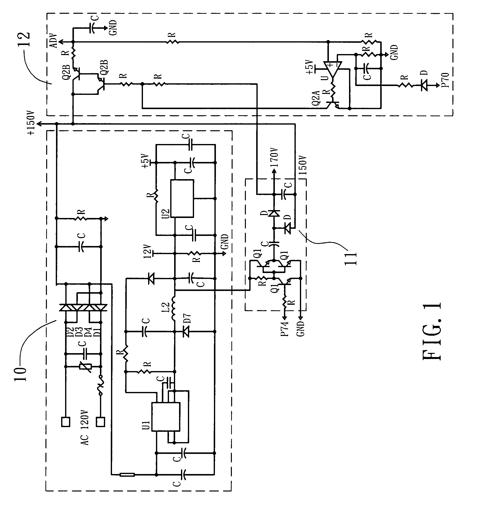
[0012]Referring to FIGS. 1˜4, a brushless motor control circuit assembly in accordance with the present invention is shown comprised of a power supply circuit 10, a booster and compensation circuit 11, a voltage regulator circuit 12, a microprocessor 20, a back electromagnetic force sensor 30, three driver circuits 40, and three output circuits 50.

[0013]The power supply circuit 10 (see FIG. 1) provides low voltage 12V / 5V and high voltage 150V for the other circuitries of the brushless motor control circuit assembly.

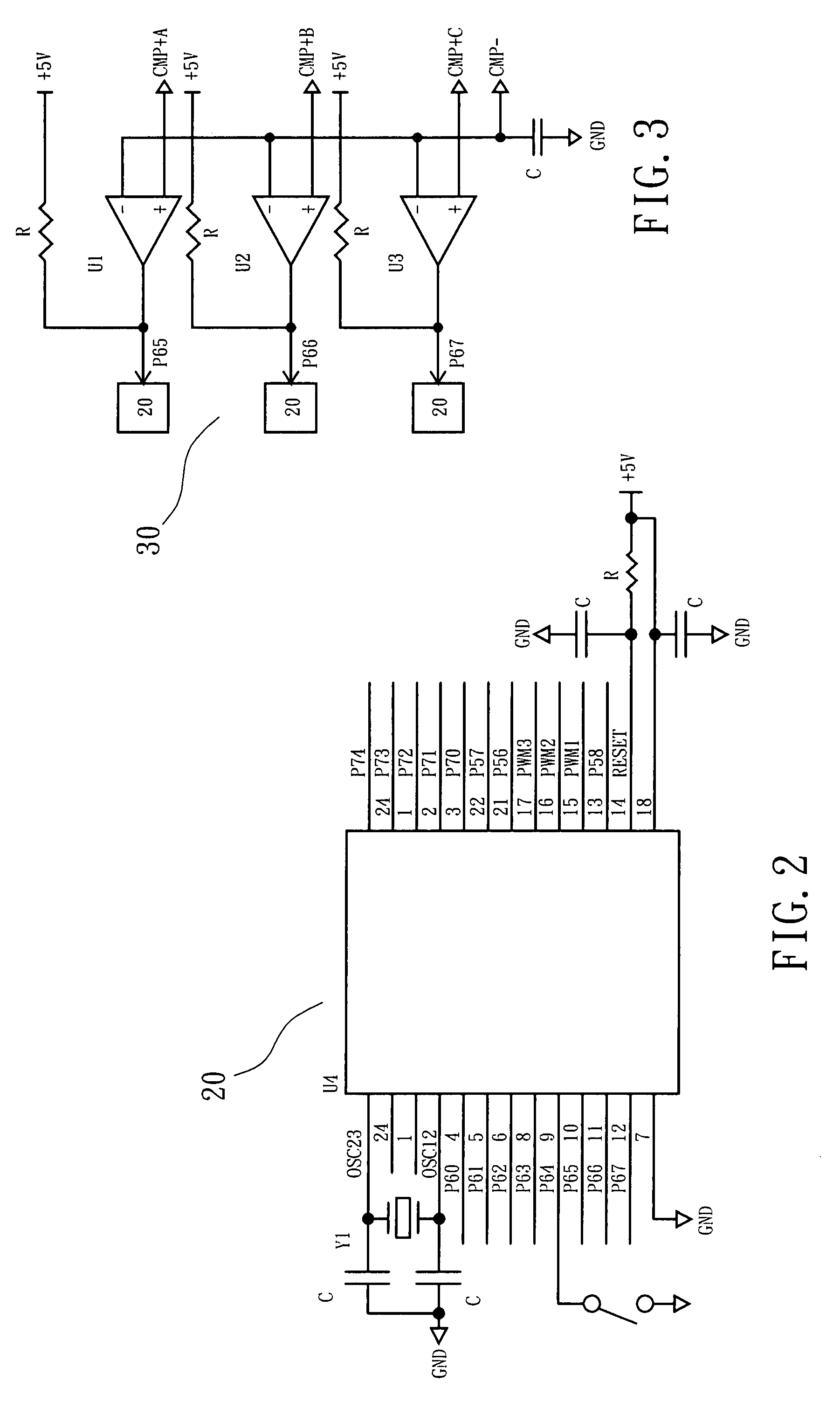
[0014]The microprocessor 20 (see FIG. 2) has memory, computation, signal reading and pulse wave modulation functions, and is adapted to receive external control signals and to output set control signals to the driver circuits 40.

[0015]The booster and compensation circuit 11 (see FIG. 1) is comprised of a plurality of transistors Q1, resistors R, capacitors C, and diodes D, and adapted to raise the 12V output voltage of the power supply circuit 10 to 170V for the driver ci...


PUM


Abstract

A power-saving, high-performance, low-noise brushless motor control circuit assembly is disclosed formed of a power supply circuit, a booster and compensation circuit, a voltage regulator circuit, a microprocessor, a back electromagnetic force sensor, three driver circuits, and three output circuits. By means of detecting back electromagnetic force, the magnetic pole position of the brushless motor is known accurately, ensuring accurate operation control. By means of providing a high voltage to drive the drive circuits, the field effect transistors of the output circuits are operated under full conduction, saving much power consumption and lowering the working temperature of the brushless motor.

Description

BACKGROUND OF THE INVENTION[0001]1. Field of the Invention[0002]The present invention relates to ceiling fans and more specifically, to a motor control circuit assembly for use in a ceiling fan to control the operation of the brushless motor.[0003]2. Description of the Related Art[0004]In a brushless motor type ceiling fan, a Hall effect sensor used to detect the change of magnetic pole position of the rotor, and a field effect transistor is necessary for output drive. The voltage of the field effect transistor is relatively low, and therefore the field effect transistor is not in “full conduction” for full power mode, i.e., the power factor is at a low level, wasting much electricity and releasing much heat.[0005]Further, PWM (Pulse-width modulation) is commonly used in the control of the speed of a brushless motor in that involves the modulation of its duty cycle to control the amount of power sent to the load. It is used to control the supply of electrical power to the brushless ...

Claims


Application Information

Patent Timeline
Patent Type & Authority Patents(United States)
IPC IPC(8): H02P6/00H02P6/14H02P6/16H02P6/18
CPCH02P6/24H02P6/22
Inventor LEE, HSIEN-MENG
Owner LEE HSIEN MENG
Why Eureka
Try Eureka