Synchronously lifted supporting leg

A synchronous lifting and outrigger technology, applied in the direction of lifting vehicle parts, vehicle maintenance, transportation and packaging, can solve the problems of difficult maintenance, easy to slide down and displacement, unable to work stably, and achieve short lifting time, The effect of improving the stability of the base station and improving the security

Active Publication Date: 2012-04-11
电联工程技术股份有限公司
View PDF4 Cites 7 Cited by
  • Summary
  • Abstract
  • Description
  • Claims
  • Application Information

AI Technical Summary

Problems solved by technology

[0003] 1. After the outrigger rises to any height, the self-locking function is lacking, and it is easy to slide down and shift, and cannot work stably at any height during the lifting process;
[0004] 2. Sequential lifting between each section of the arm, or use manual pins one by one, the lifting speed is slow;
[0005] 3. The distance between the outriggers is small, and the wind resistance of the base station is weak;
[0006] 4. The outriggers cannot be hidden, which will a

Method used


Image

  • Synchronously lifted supporting leg
  • Synchronously lifted supporting leg
  • Synchronously lifted supporting leg

Examples


Embodiment Construction

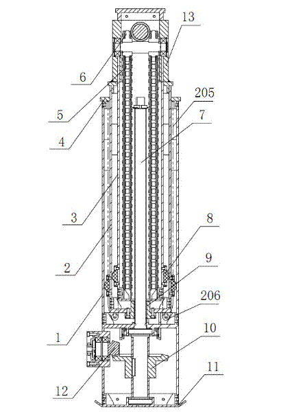
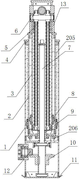
[0032] The present invention will be further described below in conjunction with specific examples, but the present invention is not limited to these specific implementations. Those skilled in the art will realize that the present invention covers all alternatives, modifications and equivalents as may be included within the scope of the claims.

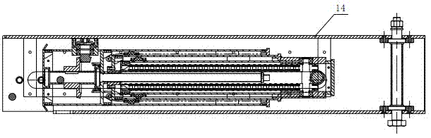
[0033] see figure 1 , figure 2 , a synchronous lifting leg, including n joint arms that are sequentially socketed from outside to inside base joint arm 1, second joint arm 2, third joint arm 3, ???, n joint arms, n≥3, the base The bottom of the joint arm 1 is connected with the bottom plate 11 placed on the ground, and a screw rod 7 is pierced in the joint arm, and a nut 9 is set on the screw rod 7, and the nut 9 is connected with the bottom of the second joint arm 2. The screw rod 7 is connected with the driver that drives it to rotate, and a plurality of sprockets 6 are installed on the upper end of the i joint arm, i≥2, each of ...


PUM


Abstract

The invention relates to a synchronously lifted supporting leg, which comprises first to [n]th arms sleeved in sequence from outside to inside, and n is not less than 3; the bottom of the first arm is connected with a bottom plate placed on the ground; each arm is inserted with a screw rod; the screw rod is sleeved with a nut; the nut is connected with the bottom of the second arm; the screw rod is connected with a driver for driving the screw rod to rotate; a plurality of chain wheels are mounted at the upper end of the [i]th arm, and i is not less than 2; each chain wheel is wound with a chain; and the two ends of the chain are connected with the bottoms of the [i-1]th arm and [i+1]th arm respectively. When the [i]th arm is moved up, the chain wheel at the upper end of the [i]th arm is moved up at the same time so that the [i+1]th arm is pulled by the chain to move up. The synchronously lifted supporting leg provided by the invention has the advantages that: the stability of a base station is improved by using high-intensity industrial section; the arms are synchronously moved, so that the lifting time is shortened; and the working state height of the base station is reduced in a multilevel lifting manner, thereby improving safety.

Description

technical field [0001] The invention relates to a synchronous lifting leg. Background technique [0002] At present, due to the high procurement cost of emergency communication vehicles and the cumbersome management and maintenance work, the number of use is limited, which cannot meet the emergency communication needs of sudden natural disasters, emergencies, and short-term large-scale gatherings that require rapid station establishment and rapid transition. All manufacturers are looking for an emergency communication mobile base station that can completely replace emergency communication vehicles; although many new products have been released, they have many shortcomings for the product legs: [0003] 1. After the outrigger rises to any height, the self-locking function is lacking, and it is easy to slide down and shift, and cannot work stably at any height during the lifting process; [0004] 2. Sequential lifting between each section of the arm, or use manual pins one by...

Claims


Application Information

Patent Timeline
IPC IPC(8): B60S9/04
Inventor 熊晓荣何健
Owner 电联工程技术股份有限公司
Why Eureka
Try Eureka