Water-saving device

A technology for water-saving devices and water tanks, applied in water supply devices, flushing equipment with water tanks, buildings, etc., can solve problems such as high water pressure requirements, difficult to clean, loud noises, etc., and achieve the effect of low cost

Active Publication Date: 2012-04-11
GUANGDONG HEGII SANITARY WARES CO LTD
View PDF5 Cites 18 Cited by
  • Summary
  • Abstract
  • Description
  • Claims
  • Application Information

AI Technical Summary

Problems solved by technology

[0002] Existing closets generally only rely on the water discharged from the water tank to flush the bedpan. Although there are spray holes at the bottom of the bedpan, the water sprayed from the spray holes also comes from the water tank. Due to the limited height of the water tank, the water coming out of the water tank The water pressure is very low, and more water is needed to flush the bedpan; some toilets are completely flushed with pressure water such as tap water, but the water pressure is relatively high, requiring a pressure of more than 300KPa, otherwise it is difficult to flush clean, and flushing loud noise
[0003] Existing water inlet valves that feed water into the water tank of the toilet generally only have a water inlet pipe connected to an external water source and a water outlet that allows water to enter the water tank. A low water tank toilet can not reach the toilet seat due to the water discharged from the water tank. Thereby can not clean the upper wall in the closet, so there is also a kind of large replenishment water inlet valve specially used in the low water tank closet on the market, although this large replenishment water inlet valve has one more water outlet than the common water inlet valve, but the The outflowing water flows to the seat ring to clean the upper wall of the toilet

Method used


Image

  • Water-saving device
  • Water-saving device
  • Water-saving device

Examples


specific Embodiment approach 2

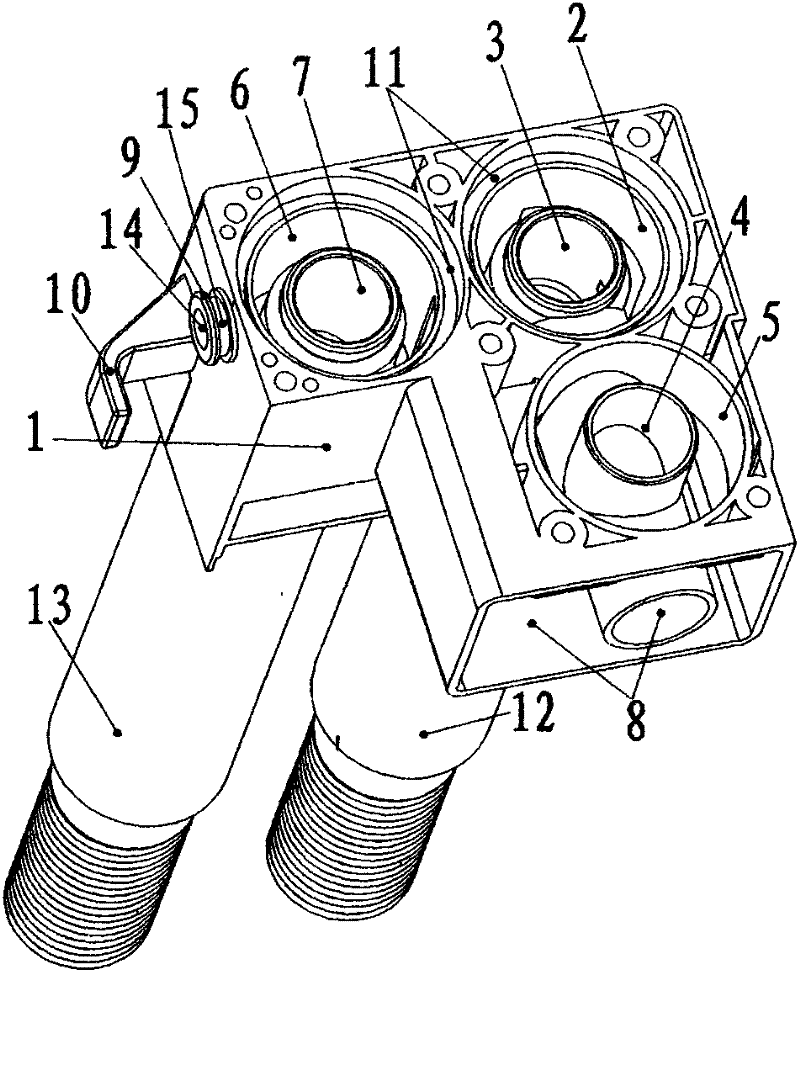
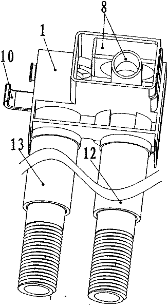
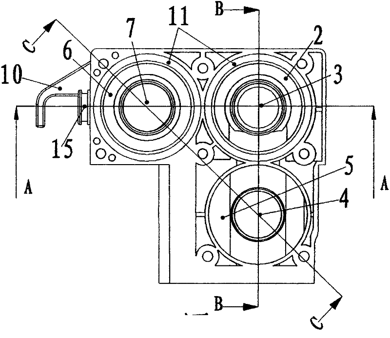
[0146] In the first embodiment, an anti-siphon valve is provided. In fact, the existence of the anti-siphon valve has no effect on the opening and closing of the main and auxiliary valves. The spool 51 moves down to cover the water inlet cavity 4 of the anti-siphon valve, and the air can enter the valve from the anti-siphon ventilation groove 19 connected up and down on the main valve cover 16, so that the negative pressure generated by the tap water pipeline will not affect the spray pipe 13. It plays a role with the water outlet pipe 49 and the water supply pipe 48, so that the water in the water tank and the bedpan can not be sucked back; if the above factors are not considered, the anti-siphon valve can be omitted. Anti-siphon spool 51 and the anti-siphon ventilation groove 19 connected up and down on the main valve cover 16 are blocked, which means that there is no anti-siphon valve, and the original anti-siphon valve inlet chamber 4 and anti-siphon valve outlet chamber 5 ...


PUM


Abstract

The invention provides a water-saving device which is installed in a water tank of a water closet, is used for feeding water into the water tank, and is used for pushing water flowing from the water tank of the water closet into a bedpan. The water-saving device comprises a water inlet pipe, a main valve, an auxiliary valve, an injection pipe and a water outlet, wherein the water inlet pipe is connected with an external water source; the main valve is communicated with the water inlet pipe; the auxiliary valve is adjacent to the main valve; the injection pipe is communicated with the auxiliary valve; the water outlet is used for discharging water into the water tank; the auxiliary valve controls water to be sprayed to the middle or bottom of the bedpan or the bottom of an inlet of a blow-off line; and the main valve controls water to be fed into the water tank of the water closet, and controls the auxiliary valve to be opened. In the invention, the water discharged from the water tank is pushed by the water pressure of the external water source for flushing, thereby effectively solving the problem of large water consumption. The water-saving device has the advantages of little water consumption and low cost and is simple and convenient to install.

Description

technical field [0001] The invention relates to a water-saving device, in particular to a water-saving device installed in a toilet water tank. Background technique [0002] Existing closets generally only rely on the water discharged from the water tank to flush the bedpan. Although there are spray holes at the bottom of the bedpan, the water sprayed from the spray holes also comes from the water tank. Due to the limited height of the water tank, the water coming out of the water tank The water pressure is very low, and more water is needed to flush the bedpan; some toilets are completely flushed with pressure water such as tap water, but the water pressure is relatively high, requiring a pressure of more than 300KPa, otherwise it is difficult to flush clean, and flushing Sometimes there will be a loud noise. [0003] Existing water inlet valves that feed water into the water tank of the toilet generally only have a water inlet pipe connected to an external water source an...

Claims


Application Information

Patent Timeline
Patent Type & Authority Applications(China)
IPC IPC(8): E03D1/36E03D1/33
Inventor 虞吉伟
Owner GUANGDONG HEGII SANITARY WARES CO LTD
Why Eureka
Try Eureka