
Apparatus for actuating a positive shifting element shiftable at least between two shifting positions

A technology for shifting elements and gear postures, applied to elements with teeth, transmission control, belts/chains/gears, etc., which can solve problems such as high sealing costs

Inactive Publication Date: 2012-04-11
ZF FRIEDRICHSHAFEN AG +1
View PDF9 Cites 7 Cited by
  • Summary
  • Abstract
  • Description
  • Claims
  • Application Information

AI Technical Summary

Problems solved by technology

However, the function of such a transmission device can only be ensured with considerable sealing effort in the area of ​​the delivery lines and in the area of ​​the shifting element itself

Method used


Image

  • Apparatus for actuating a positive shifting element shiftable at least between two shifting positions
  • Apparatus for actuating a positive shifting element shiftable at least between two shifting positions
  • Apparatus for actuating a positive shifting element shiftable at least between two shifting positions

Examples


Embodiment Construction

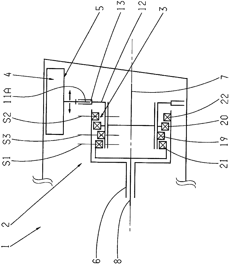
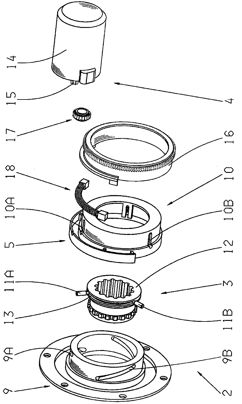
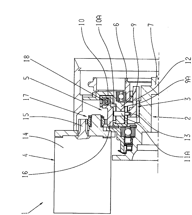
[0034] figure 1 Shown is a transmission device 1 with a device 2 for actuating form-locking shifting elements that can be shifted between three shifting positions S1, S2 and S3, with a drive device 4 and figure 2 and image 3 The drive conversion device 5 shown in detail in FIG. 2 is used to convert the rotational drive movement of the drive device 4 into a translational operating movement of the form-fitting shifting element.

[0035] Both in the first shifting position S1 and in the second shifting position S2, the two transmission shafts 6 and 7 or 7 and 8 are connected to each other in a rotationally fixed manner via the form-locking shifting element 3 , while in the first shifting position S1 and in the second shifting position S2 In the third shifting position S3 of the shifting element 3 , the transmission shafts 6 and 7 or 7 and 8 are separated from each other.

[0036] The drive conversion device 5 comprises a first structural element 9 with three control curves 9A...


PUM


Abstract

The invention describes an apparatus (2) for actuating a positive shifting element (3), which can be shifted at least between two shifting positions, of a transmission device having a drive device (4) and a drive converter device (5) for converting a rotatory drive motion of the drive device (4) into a translatory actuating motion of the positive shifting element (3). By means of the shifting element (3), two gear shafts are non-rotatably coupled to each other in one shifting position (1), and in another shifting position of the shifting element the gear shafts are decoupled from each other. According to the invention, the drive converter device (5) comprises a first component (9) having at least one control cam (9A, 9B) and a second component (10) operatively connected thereto, which in the region of the control cam (9A, 9B) are coupled to a component (12) of the positive shifting element (3), said component being axially movable and non-rotatably coupled to one of the gear shafts.

Description

technical field [0001] The invention relates to a device of the type defined in detail in the preamble of claim 1 for actuating a form-fitting shifting element which can be shifted between at least two shifting positions. Background technique [0002] In transmission devices known from practice, rotating structural elements such as drive shafts or so-called freewheels are connected or disconnected from the force flow of the transmission device via shifting elements, depending on the operating state, in order to be able to represent Different gear ratios or ranges of gear ratios of a transmission and can be switched between. [0003] If the shifting element is designed as a friction-locking shifting element, the transmission ratio change can preferably be carried out without interruption of tractive force with high driving comfort. Undesirably, however, disengaged frictional shifting elements are characterized by drag torques which adversely affect the efficiency of the tran...

Claims


Application Information

Patent Timeline
Patent Type & Authority Applications(China)
IPC IPC(8): F16H61/32F16H63/18F16H63/30
CPCF16H2063/3089F16H2063/3056F16H63/304F16H61/32
Inventor 托马斯·罗泽迈尔克里斯托夫·佩尔兴贝恩德-罗伯特·赫恩
Owner ZF FRIEDRICHSHAFEN AG
Learn More