
Electrically-powered vehicle and method for controlling the same

a technology of electric vehicles and electric motors, applied in the direction of vehicle position/course/altitude control, process and machine control, instruments, etc., can solve the problems of vehicle vibration and vehicle vibration, and achieve the effect of reducing vehicle vibration and improving driving comfor

Active Publication Date: 2013-07-04
TOYOTA JIDOSHA KK
View PDF9 Cites 25 Cited by
  • Summary
  • Abstract
  • Description
  • Claims
  • Application Information

AI Technical Summary

Benefits of technology

This patent is about a way to make electric vehicles that have less vibrations, which makes them more comfortable to drive. The invention controls the electric motors to reduce the vibrations, which can happen when the vehicle is moving. By doing this, drivers can have a better experience driving the electric vehicle.

Problems solved by technology

In the electrically-powered vehicle, when an output of the vehicle-driving electric motor is used to drive the drive wheels, a periodically varying component may occur to the rotational speed of the electric motor to thereby cause vibrations of the vehicle.
When the engine is started or stopped while being intermittently operated, speed variations of the vehicle can cause vehicle's vibrations.

Method used


Image

  • Electrically-powered vehicle and method for controlling the same
  • Electrically-powered vehicle and method for controlling the same
  • Electrically-powered vehicle and method for controlling the same

Examples


Embodiment Construction

[0038]In the following, embodiments of the present invention will be described in detail with reference to the drawings. In the drawings, the same or corresponding components are denoted by the same reference characters, and a description thereof will not be repeated in principle.

[0039]System Configuration

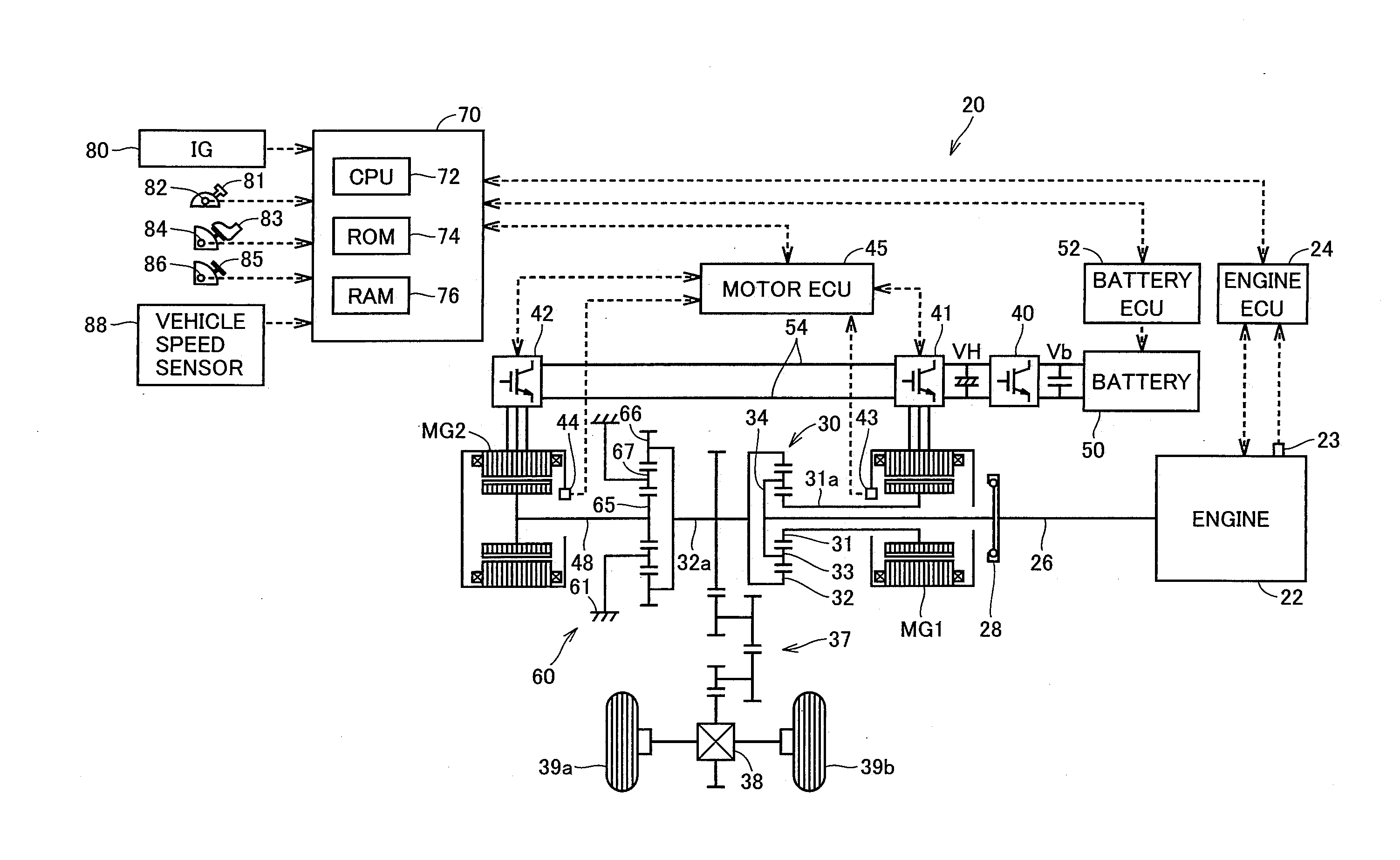
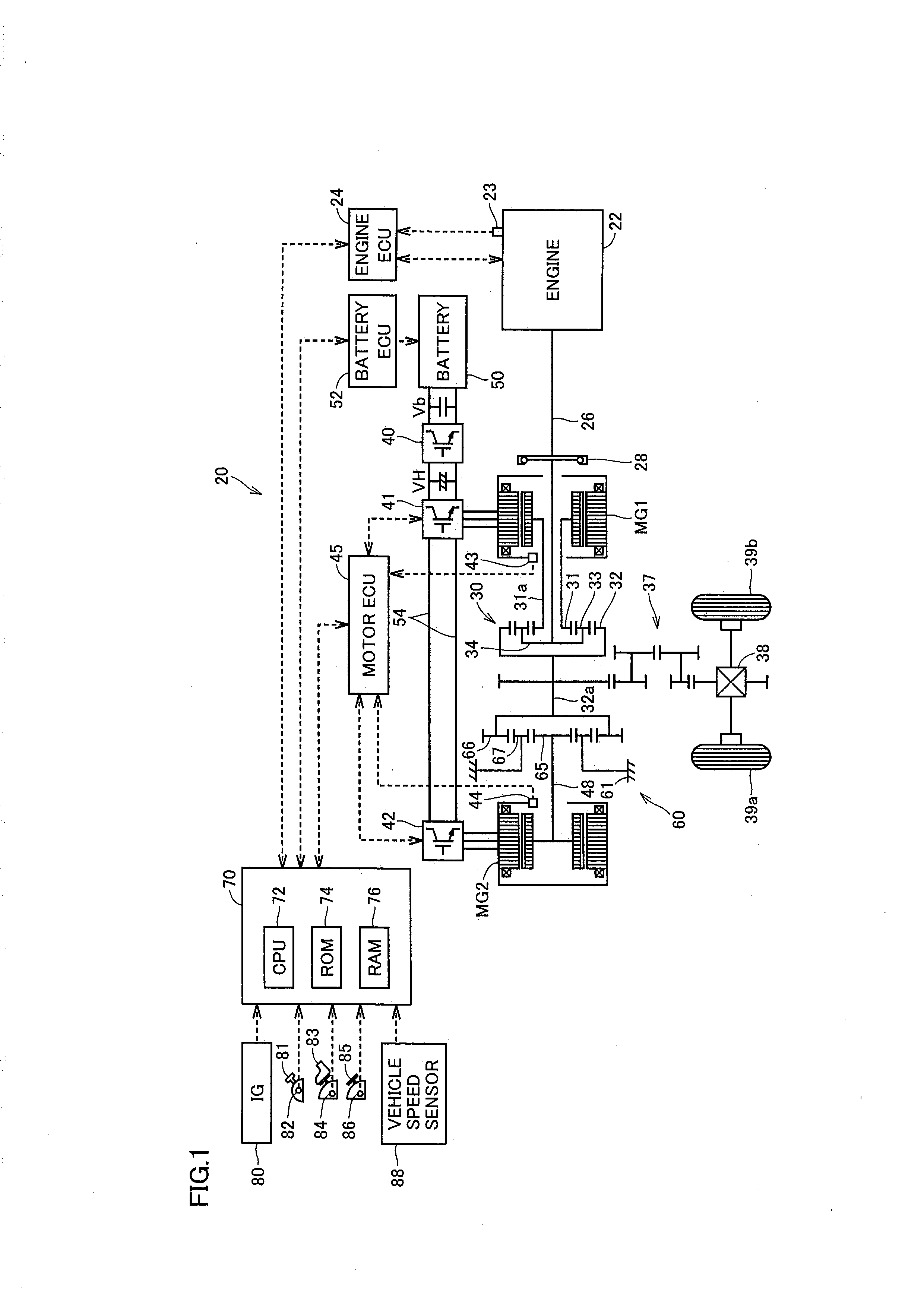
[0040]FIG. 1 is a configuration diagram showing a schematic configuration of a hybrid vehicle illustrated as a typical example of the electrically-powered vehicle in an embodiment of the present invention.

[0041]Referring to FIG. 1, hybrid vehicle 20 in a first embodiment includes an engine 22, a crankshaft 26 serving as an output shaft of engine 22, a torsional damper 28, and a three-shaft power split device 30. Crankshaft 26 is connected through torsional damper 28 to power split device 30.

[0042]Hybrid vehicle 20 further includes motor generators MG1, MG2 serving as electric motors for driving the vehicle, a transmission 60, and a hybrid-adapted electronic control unit (hereinafte...


PUM


Abstract

A hybrid vehicle includes a plurality of motor generators and an engine for generating a vehicle-driving force. A motor ECU controls the motor generators in accordance with respective torque command values for the motor generators. The motor ECU selects a motor generator used for performing vibration-reduction control, based on the operating state of the motor generators each. The output torque of the motor generator used for the vibration-reduction control is controlled so that a compensation torque corresponding to a periodic vibration-reduction torque component for cancelling out a periodic variation component of the rotational speed of drive wheels is superimposed on the torque for generating the vehicle-driving force.

Description

[0001]This is a 371 national phase application of PCT / JP2010 / 065133 filed 3 Sep. 2010, the contents of which are incorporated herein by reference.FIELD OF THE INVENTION[0002]The present invention relates to an electrically-powered vehicle and a method for controlling the electrically-powered vehicle, and more specifically to motor control for reducing vibrations of the vehicle.BACKGROUND OF THE INVENTION[0003]In recent years, electrically-powered vehicles mounted with an electric motor for driving the vehicle, such as hybrid vehicle, electric vehicle, fuel cell vehicle and the like have been of interest as environmentally-friendly vehicles. In the electrically-powered vehicle, when an output of the vehicle-driving electric motor is used to drive the drive wheels, a periodically varying component may occur to the rotational speed of the electric motor to thereby cause vibrations of the vehicle. Such a phenomenon, for example, can occur when the vehicle accelerates or decelerates.[000...

Claims


Application Information

Patent Timeline
Patent Type & Authority Applications(United States)
IPC IPC(8): B60W20/00
CPCB60K6/445Y02T10/644B60W10/08B60W30/20B60W2030/206B60W2710/083Y02T10/6239B60W20/00Y10S903/903H02P21/05H02P23/04B60W2510/08Y02T10/643Y02T10/7275B60L15/20Y02T10/72Y02T10/64Y02T10/62
Inventor HASHIMOTO, TOSHIYA
Owner TOYOTA JIDOSHA KK
Learn More