Vehicle output control limiter

a technology for limiting torque and vehicle output, which is applied in the direction of electric control, gearing, instruments, etc., can solve the problems of poor drivability, customer dissatisfaction, and the impact so as to minimize the effect of transmission gear separation, minimize the impact of torque change, and improve drive comfor

Inactive Publication Date: 2002-09-19
FORD GLOBAL TECH LLC
View PDF0 Cites 25 Cited by
  • Summary
  • Abstract
  • Description
  • Claims
  • Application Information

AI Technical Summary

Benefits of technology

[0007] By limiting a change in powertrain output when transmitted torque is within a predetermined range, it is possible to provide improved drive comfort with minimimal impact on performance feel. In other words, limiting the change in torque minimizes the effects of transmission gear separation, or "clunk". However, since torque can be limited only under conditions where transmission gear separation occurs, other driving conditions are not hindered by any torque limitations.

Problems solved by technology

The inventors herein have recognized a disadvantage if conventional methods of powertrain output control are used during tip-out and tip-in situations.
In particular, if the accelerator pedal is released and subsequently engaged, poor drivability may be experienced due transmission gears lash.
This series of events produces an impact, or clunk, resulting in poor drivability and customer dissatisfaction.
When the gears again make contact, they do so dynamically, resulting in an undesirable impact.
This disadvantage is exacerbated when the operator returns the accelerator pedal to a depressed position, indicating a desire for increased powertrain output.
However, in this situation, the engine is producing a larger amount of torque than during deceleration because the driver is requesting acceleration.
Thus, another, more severe, impact is experienced due to the transmission lash during the zero torque transition.

Method used


Image

  • Vehicle output control limiter
  • Vehicle output control limiter
  • Vehicle output control limiter

Examples


Embodiment Construction

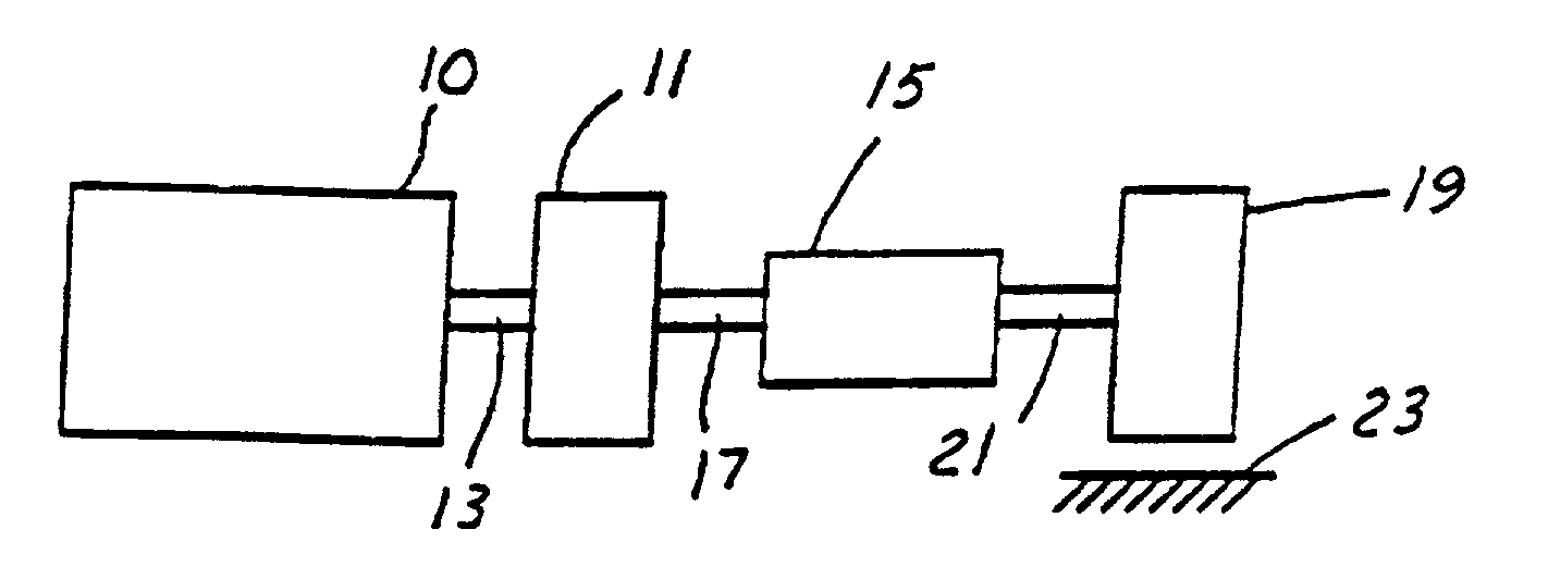
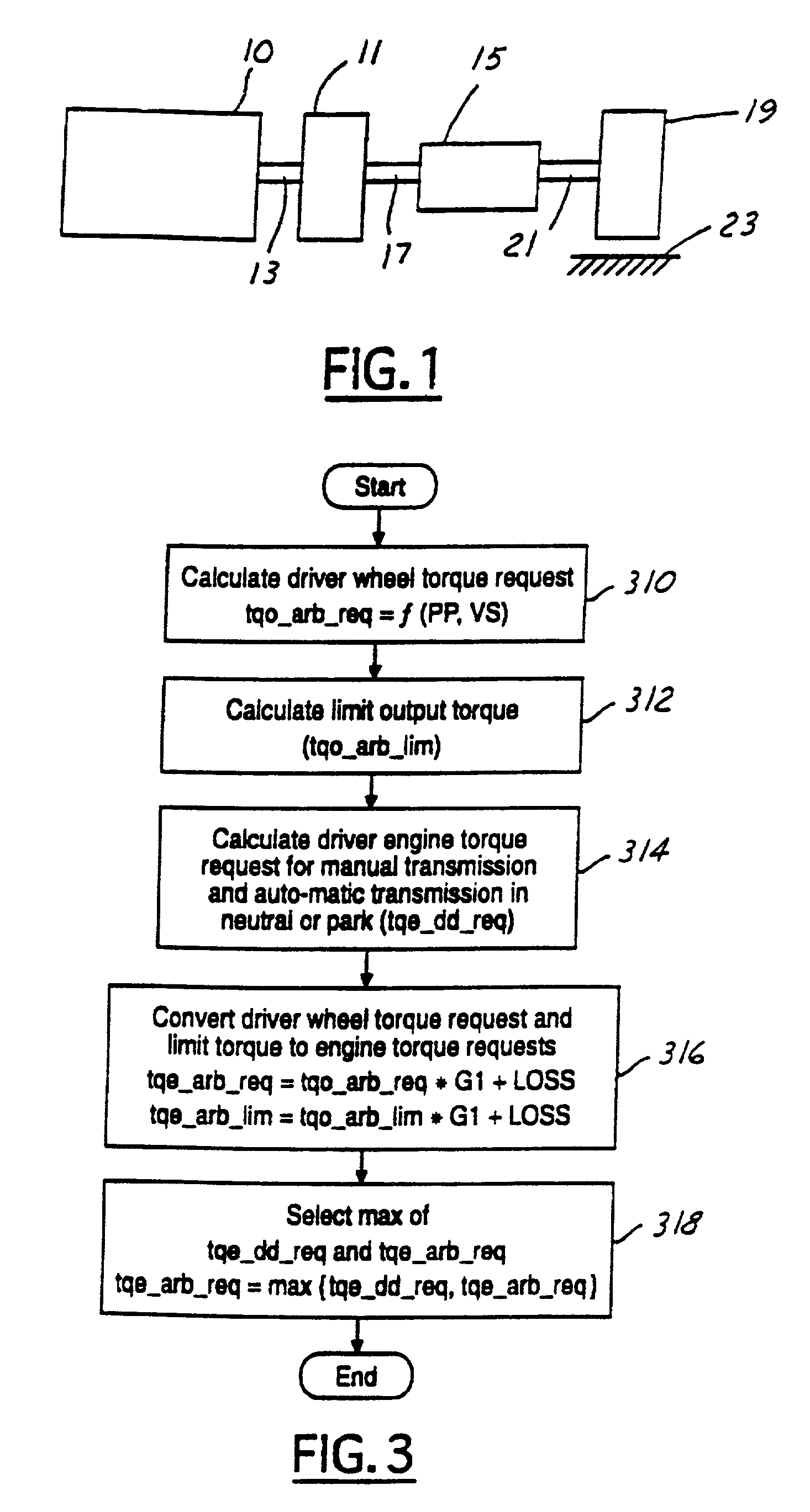
[0013] Referring to FIG. 1, internal combustion engine 10, further described herein with particular reference to FIG. 2, is shown coupled to torque converter 11 via crankshaft 13. Torque converter 11 is also coupled to transmission 15 via transmission input shaft 17. Torque converter 11 has a bypass clutch (described in FIGS. 20-23), which can be engaged, disengaged, or partially engaged. When the clutch is either disengaged or partially engaged, the torque converter is said to be in an unlocked state. Transmission 15 comprises an electronically controlled transmission with a plurality of selectable discrete gear ratios. Transmission 15 also comprises various other gears such as, for example, a final drive ratio (not shown). Transmission 15 is also coupled to tire 19 via axle 21. Tire 19 interfaces the vehicle (not shown) to the road 23. In a preferred embodiment, transmission 15 has the following driver selectable options: park (P), reverse (R), neutral (N), driver (D), and low (L)...


PUM


Abstract

A method is described for limiting a change in torque transmitted through a vehicle powertrain when in a predetermined range. Such a method minimizes transmission gear separation, or "clunk". In one approach, the rate of change of powertrain output is limited when powertrain output is near zero transmitted torque. The limitation is not used under other circumstances so as not to hinder driver performance.

Description

FIELD OF THE INVENTION[0001] The present invention relates to automotive vehicles, and more particularly to powertrain control of automotive vehicles.BACKGROUND OF THE INVENTION[0002] A vehicle powertrain typically includes a power source, such as an internal combustion engine, coupled to a gearbox, such as a transmission with various gear ratios. A powertrain controller is usually provided which controls the powertrain in part based on a driver's requests.[0003] In one system, desired powertrain output is determined based on depression of a pedal by a vehicle operator. In such a system, a strategy is needed for the situation when a driver releases the pedal, known to those skilled in the art as a tip-out. During a tip-out, the driver is indicating a desire for reduced engine output. Further, a strategy is needed for the situation when a driver depresses the pedal, known to those skilled in the art as a tip-in. During a tip-in, the driver is indicating a desire for increased engine ...

Claims


Application Information

Patent Timeline
Patent Type & Authority Applications(United States)
IPC IPC(8): B60K26/00B60W10/06B60W30/18F02D41/00F02D41/02F02D41/10F16H59/38F16H61/14F16H63/50G06F7/00
CPCB60W10/06B60W10/11B60W30/18B60W2510/0638B60W2510/1025B60W2710/105F02D41/0215F02D41/107F02D2200/1004F02D2200/1006F02D2250/18F02D2250/21F02D2400/12F16H61/143F16H63/50F16H2059/385F16H2059/144F16H2057/0012Y10T477/679Y10T477/675B60W10/04B60W30/1819
Inventor O'NEIL, BRIAN MICHAELRIEDLE, BRADLEY DEANLIGHT, DENNIS ALLENCULLEN, MICHAEL JOHN
Owner FORD GLOBAL TECH LLC
Why Eureka
Try Eureka