Rail clamping device and locomotive traction positioning system

A technology of positioning system and rail clamp, which is applied in the direction of railway braking system, brake, transportation and packaging where the braking element interacts with the track, etc. It can solve the problems that it is difficult to reliably fix the traction positioning device, and the traction positioning device cannot be applied. , to achieve the effect of reliable fixed connection

Active Publication Date: 2012-04-18
ZHUZHOU CSR TIMES ELECTRIC CO LTD
View PDF6 Cites 6 Cited by
  • Summary
  • Abstract
  • Description
  • Claims
  • Application Information

AI Technical Summary

Problems solved by technology

[0005] The invention solves the technical problems existing in the prior art that it is difficult to reliably fix the traction positioning d

Method used


Image

  • Rail clamping device and locomotive traction positioning system
  • Rail clamping device and locomotive traction positioning system
  • Rail clamping device and locomotive traction positioning system

Examples


Embodiment Construction

[0018] In order to make the technical problems, technical solutions and beneficial effects solved by the present invention clearer, the present invention will be further described in detail below in conjunction with the accompanying drawings. It should be understood that the specific embodiments described here are only used to explain the present invention, not to limit the present invention.

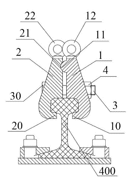
[0019] The present invention provides a rail clamp 100 for fixing a locomotive traction positioning device 300 on a steel rail 400 . figure 1 It is a structural schematic diagram of the rail clamp 100 and the rail 400 .

[0020] Such as figure 1 As shown in , the rail clamp 100 includes two opposite clamping plates for clamping the rail 400 , and a bolt 3 passing through the two clamping plates. A nut 4 is sheathed on one end of the bolt 3 . The two splints are respectively the first plate 1 and the second plate 2 , and the shapes of the inner sides of the first plate 1 and the second...


PUM


Abstract

The invention provides a rail clamping device, which is used for fixing a locomotive traction positioning device on a steel rail. The rail clamping device comprises two clamping plates which are arranged oppositely and used for clamping the steel rail, and bolts which pass through the two clamping plates, wherein one end of each bolt is sleeved with a nut; the shapes of inner side faces of the two clamping plates are matched with the shape of the steel rail; the lower ends of the two clamping plates are provided with barbs which face the steel rail; and the two barbs are clamped to the steel rail. The invention also provides a locomotive traction positioning system with the rail clamping device. A platform can be fixedly connected with the steel rail through the rail clamping device, so that the locomotive traction positioning device and the steel rail which are fixedly arranged on the platform can be reliably and fixedly connected; and the rail clamping device can be fixed at any position of the steel rail, so that the locomotive traction positioning device can be fixed at any longitudinal position of the steel rail, and can be fixed at any position of locomotives with different lengths and carriage numbers.

Description

technical field [0001] The invention relates to a test system for rail transit equipment, in particular to a rail clamp and a locomotive traction positioning system. Background technique [0002] In the application of the locomotive rolling test stand, in order to fix the locomotive on the rolling test stand, both ends of the locomotive need to be pulled so that the locomotive does not move under the action of traction. The device that pulls the two ends of the locomotive is called the traction positioning device. Therefore, the fixing of the traction positioning device is more important. In the past, only the rolling test was performed on the locomotive head, and the length of the locomotive head was within a certain range, so the traction positioning device can be fixed by the embedded platform. The pre-buried platform is pre-buried in the test pit in advance, and the length range is controlled within a certain range and cannot be expanded. [0003] But now, due to the ...

Claims


Application Information

Patent Timeline
IPC IPC(8): B61H7/12G01M17/08
Inventor 夏应贵倪平涛
Owner ZHUZHOU CSR TIMES ELECTRIC CO LTD
Why Eureka
Try Eureka