

Lighting device, display device, and television receiver
A technology for a lighting device and a display device, which is applied in the fields of display devices, television receivers, and lighting devices, and can solve the problems of increasing brightness, increasing the number of light sources, increasing power consumption, etc., achieving good visual recognition, suppressing uneven display, good display effect
- Summary
- Abstract
- Description
- Claims
- Application Information
AI Technical Summary
Problems solved by technology
Method used
Image

Examples
Embodiment approach 1
[0081] use Figure 1 to Figure 10 Embodiment 1 of the present invention will be described.
[0082] First, the configuration of a television receiver TV including a liquid crystal display device 10 will be described.
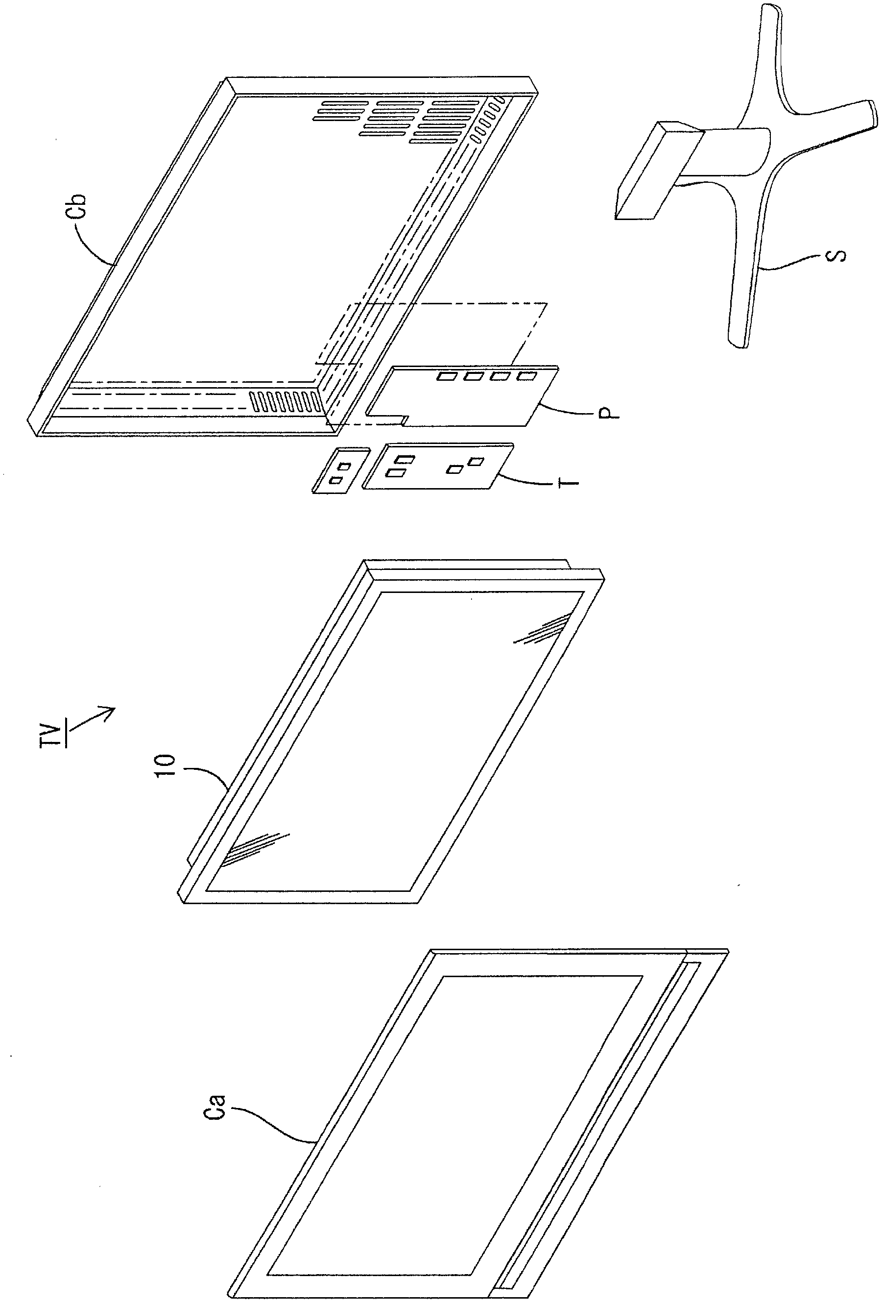
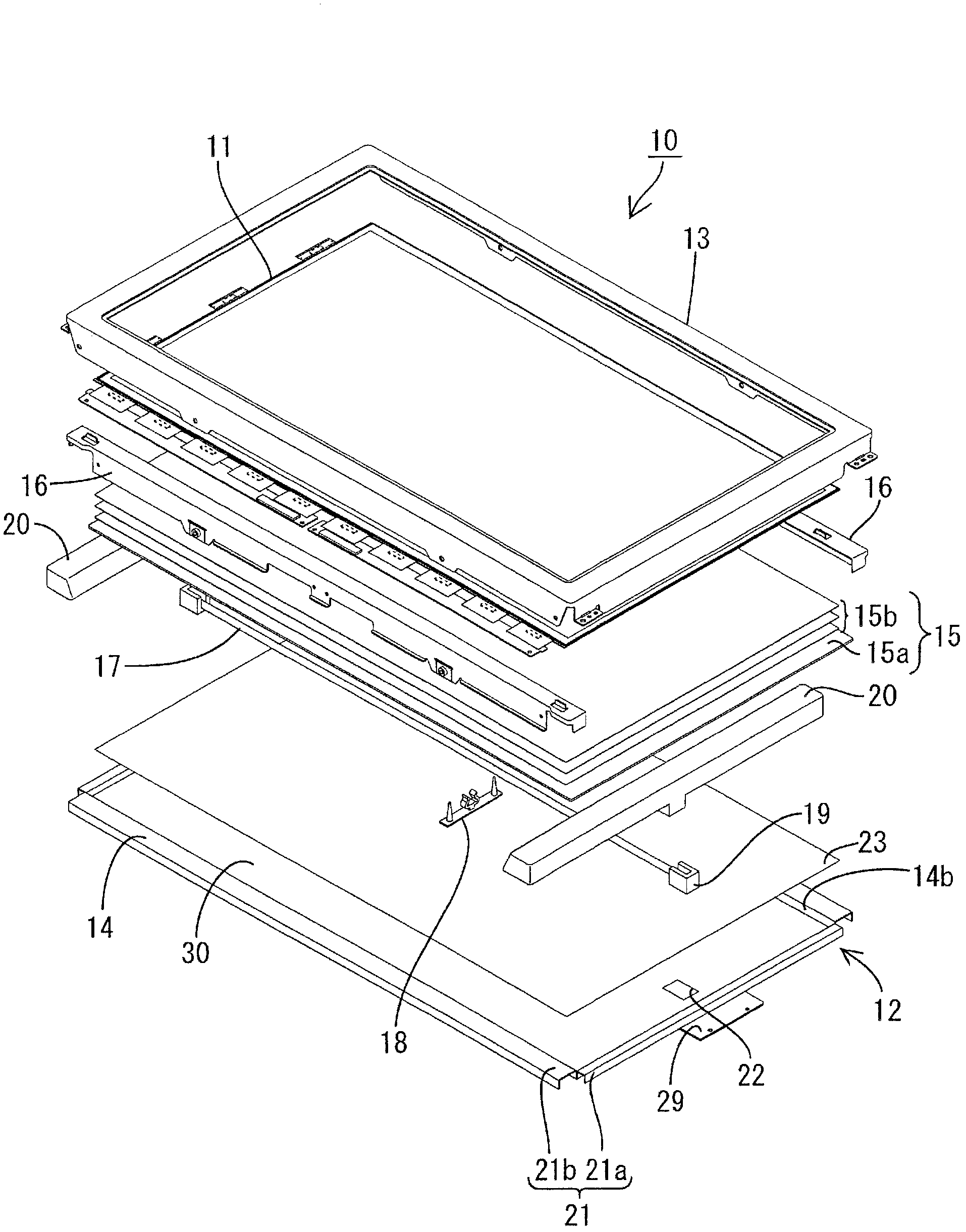
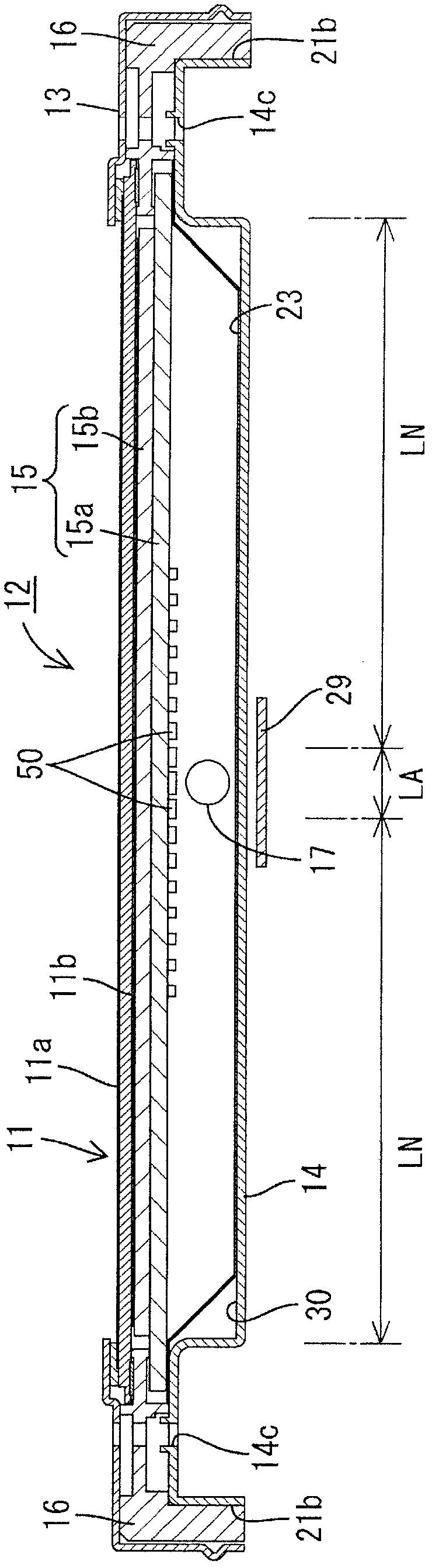
[0083] Such as figure 1 As shown, the television receiver TV according to the present embodiment is configured to include a liquid crystal display device 10 , front and rear cabinets Ca and Cb for accommodating the liquid crystal display device 10 , a power supply P, a tuner T, and a stand S. The liquid crystal display device (display device) 10 has a horizontally long square shape as a whole, and is housed in a vertical state. Such as figure 2 As shown, the liquid crystal display device 10 includes a liquid crystal panel 11 as a display panel and a backlight device (illumination device) 12 as an external light source, and these are integrally held by a frame-shaped outer frame 13 or the like.
[0084] Next, the liquid crystal panel 11 and the backlight un...
Embodiment approach 2
[0141] Use below Figure 17 to Figure 20 Embodiment 2 of the present invention will be described. In this Embodiment 2, the arrangement|positioning pattern of a light source is changed from Embodiment 1, and it is the same as that of Embodiment 1 above other than that. The same reference numerals are assigned to the same parts as those in Embodiment 1 above, and overlapping descriptions will be omitted.
[0142] Figure 17 is a plan view showing a schematic configuration of a chassis included in a backlight unit, Figure 18 It is a schematic diagram showing the arrangement pattern of the light reflection part formed on the surface facing the cold cathode tube in the diffuser plate, Figure 19 is showing Figure 18 The coordinate diagram of the light reflectance of the E-E' line of the diffuser plate, Figure 20 is showing Figure 18 Graph of the variation of light reflectance on the F-F' line of the diffuser plate. In addition, in Figure 19 In , the horizontal axis sh...
Embodiment approach 3
[0153] Use below Figure 21 to Figure 25 Embodiment 3 of the present invention will be described. In this Embodiment 3, the configuration pattern of the light source is further changed from that of Embodiment 1, and the rest is the same as that of Embodiment 1 described above. The same reference numerals are assigned to the same parts as those in Embodiment 1 above, and overlapping descriptions will be omitted.
[0154] Figure 21 is an exploded perspective view showing a schematic configuration of a liquid crystal display device, Figure 22 is a schematic plan view of a base showing an arrangement pattern of LED light sources, Figure 23 It is a schematic diagram showing the arrangement pattern of the light reflection part formed on the surface facing the LED light source in the diffuser plate, Figure 24 is a graph showing the light reflectance of the G-G' line of the diffuser plate, Figure 25 It is a graph showing the light reflectance of the J-J' line of the diffuser...
PUM
| Property | Measurement | Unit |
|---|---|---|
| haze | aaaaa | aaaaa |
Abstract
Description
Claims
Application Information