

Illuminating apparatus, display apparatus and television receiving apparatus
A technology for lighting devices and display devices, which is applied to lighting devices, components of lighting devices, lighting and heating equipment, etc., and can solve problems such as the decrease in illumination brightness of backlight devices, uneven brightness, and display quality degradation of liquid crystal display devices, etc. Problems, to achieve uniform lighting brightness distribution, suppress display unevenness, excellent effect of display unevenness
- Summary
- Abstract
- Description
- Claims
- Application Information
AI Technical Summary
Problems solved by technology
Method used
Image

Examples
Embodiment approach 1
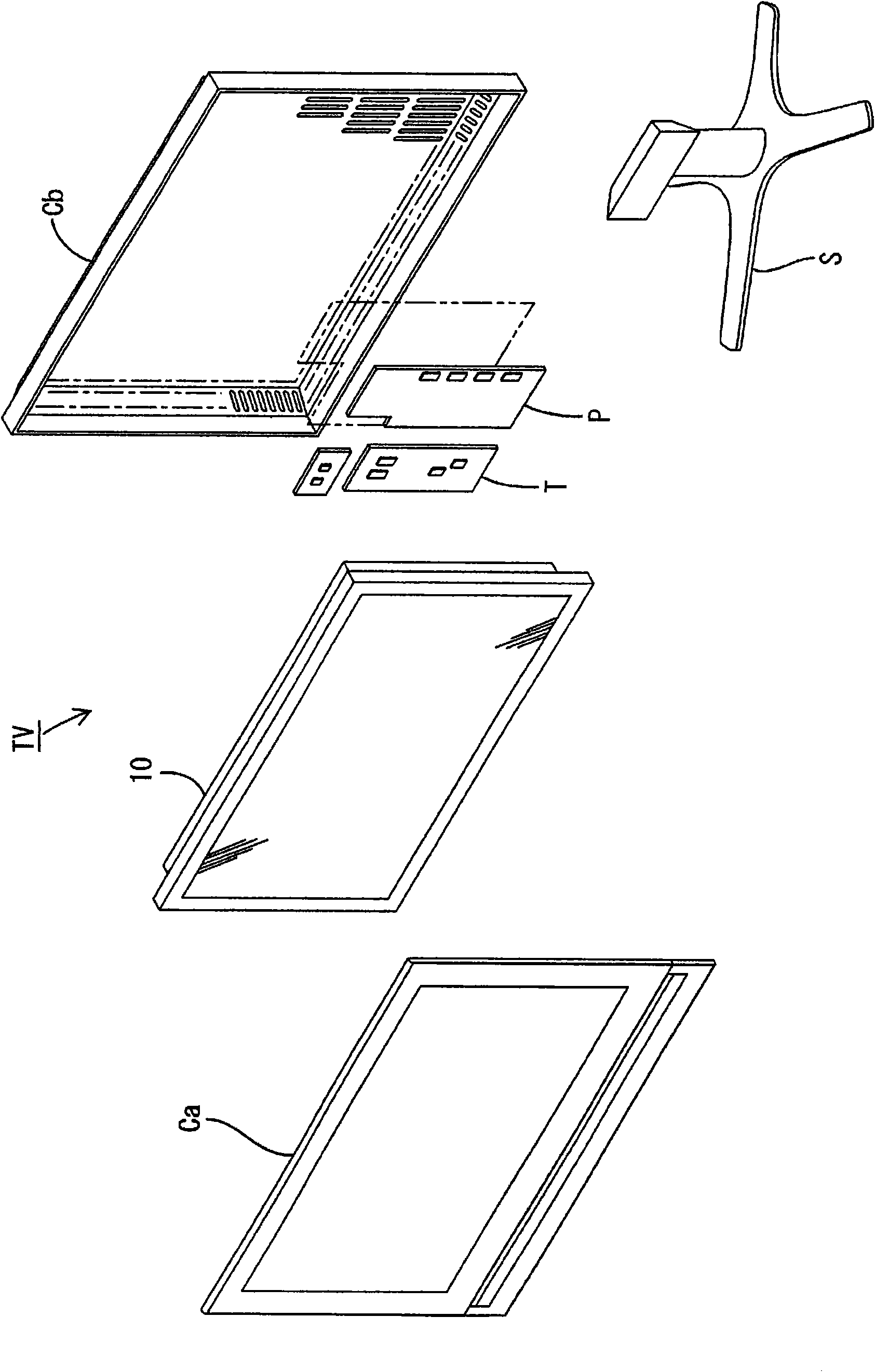
[0064] according to Figure 1 to Figure 9 Embodiment 1 of the present invention will be described. First, use Figure 1 to Figure 6 The configuration of a television receiver TV having a liquid crystal display device 10 will be described.
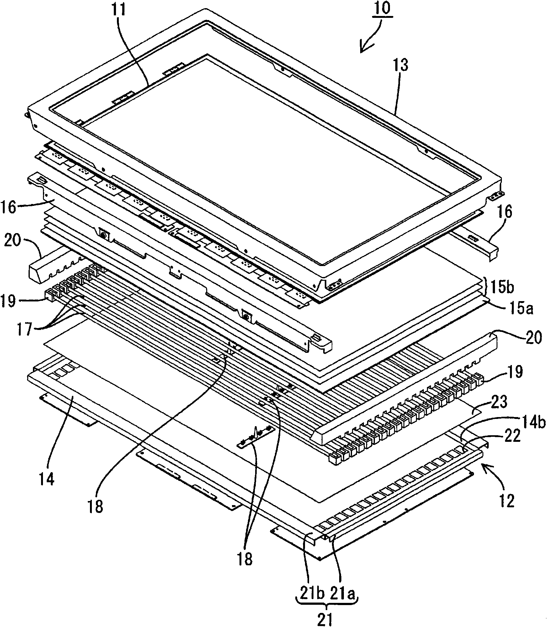
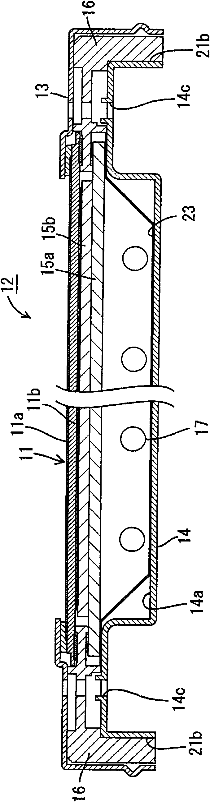
[0065] figure 1 It is an exploded perspective view showing a schematic configuration of a television receiver according to this embodiment, figure 2 yes means figure 1 An exploded perspective view of the schematic structure of the liquid crystal display device included in the television receiving device of image 3 yes means figure 2 A cross-sectional view of the cross-sectional structure of the liquid crystal display device along the short-side direction, Figure 4 yes means figure 2 A cross-sectional view of the cross-sectional structure of the liquid crystal display device along the long-side direction, Figure 5 yes means figure 2 A cross-sectional view of the structure of the lamp clip possessed by the liquid crystal displ...
Embodiment approach 2
[0116] Next, use Figure 10 and Figure 11 Embodiment 2 of the present invention will be described. In this second embodiment, the structure in which the shape of the spacer is changed is shown, and the rest is the same as the above-mentioned embodiment. The same reference numerals are assigned to the same parts as those in the above-mentioned embodiment, and repeated explanations will be omitted.
[0117] Such as Figure 10 As shown, the spacer 40B has a structure in which a plurality of substantially semi-cylindrical spacers 41B are arranged side by side on the substrate piece 42B. The end portion of the spacer 41B facing the cold cathode tube 17 is a strip line 43B, and has circumferential surfaces 44B and 45B that are convexly curved from the strip line 43B toward the substrate piece 42B. The spacers 41B are arranged so that the strip lines 43B coincide with the short side direction of the substrate piece 42B (spacer piece 40B).
[0118] The spacer sheet 40B is attach...
Embodiment approach 3
[0120] Next, use Figure 12 and Figure 13 Embodiment 3 of the present invention will be described. In this third embodiment, a structure in which the shape of the spacer is changed is shown, and the rest are the same as the above-mentioned embodiment. The same reference numerals are assigned to the same parts as those in the above-mentioned embodiment, and repeated explanations will be omitted.
[0121] Such as Figure 12 As shown, the spacer 40C adopts a structure in which a plurality of substantially corrugated spacers 41C having arc-shaped recesses on the end surface opposite to the cold cathode tube 17 are arranged on the substrate piece 42C. The end surface of the spacer 41C opposite to the cold cathode tube 17 is recessed in an arc shape to form a concave portion 43C, and has curved surfaces 44C, 45C that are concavely curved from the concave portion 43C to the substrate sheet 42C to form a widened bottom. In addition, the curvature formed by the arc of the grooved ...
PUM
 Abstract
Description
Claims
Application Information