Illumination device, display device, and television receiving device

A technology for lighting devices and display devices, which is applied in the fields of display devices, TV receivers, and lighting devices. It can solve problems such as hindering the thinning of the base, and achieve the effects of excellent TV images, uniform lighting brightness distribution, and excellent display quality.

Inactive Publication Date: 2011-01-19
SHARP KK
View PDF1 Cites 6 Cited by
  • Summary
  • Abstract
  • Description
  • Claims
  • Application Information

AI Technical Summary

Problems solved by technology

[0007] However, according to the above structure, since the reinforcing metal member is arranged on the top plate portion of the base, the reinforcing metal member becomes a factor hindering the thinning of the base.

Method used


Image

  • Illumination device, display device, and television receiving device
  • Illumination device, display device, and television receiving device
  • Illumination device, display device, and television receiving device

Examples


Embodiment approach 1

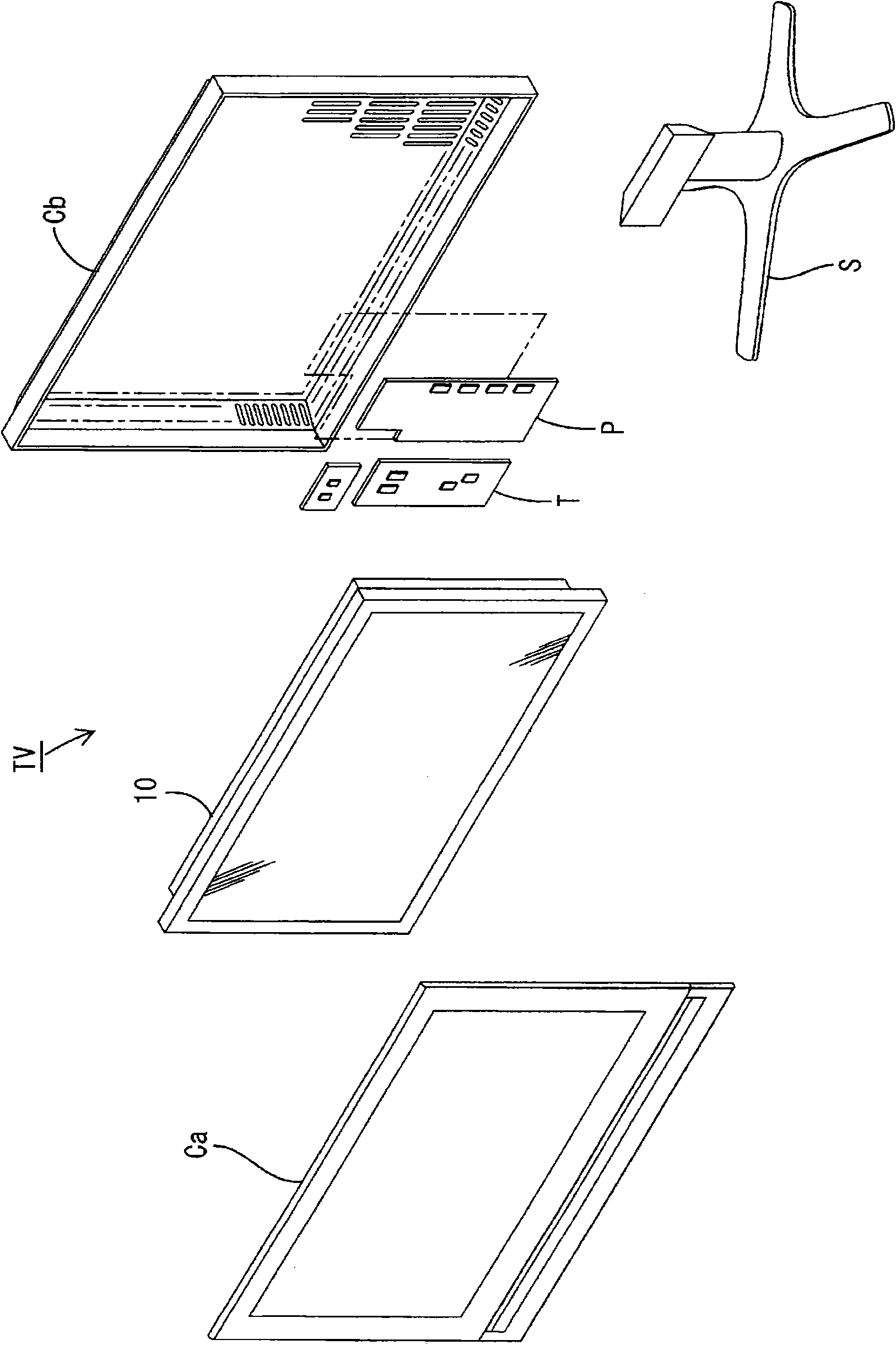
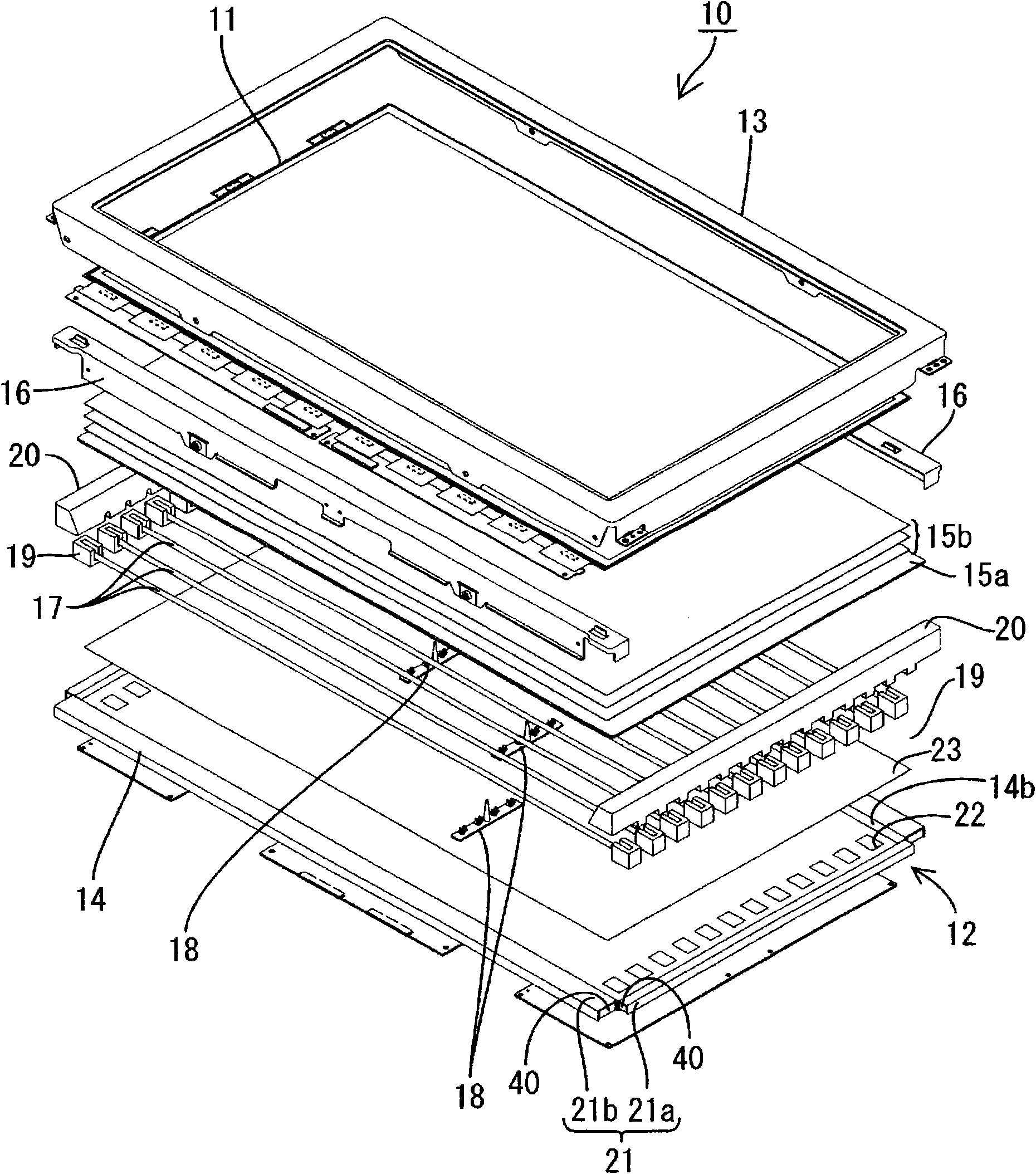
[0067] use Figure 1 to Figure 6 Embodiment 1 of the present invention will be described. In this embodiment, a television receiver TV having a liquid crystal display device 10 is exemplified.

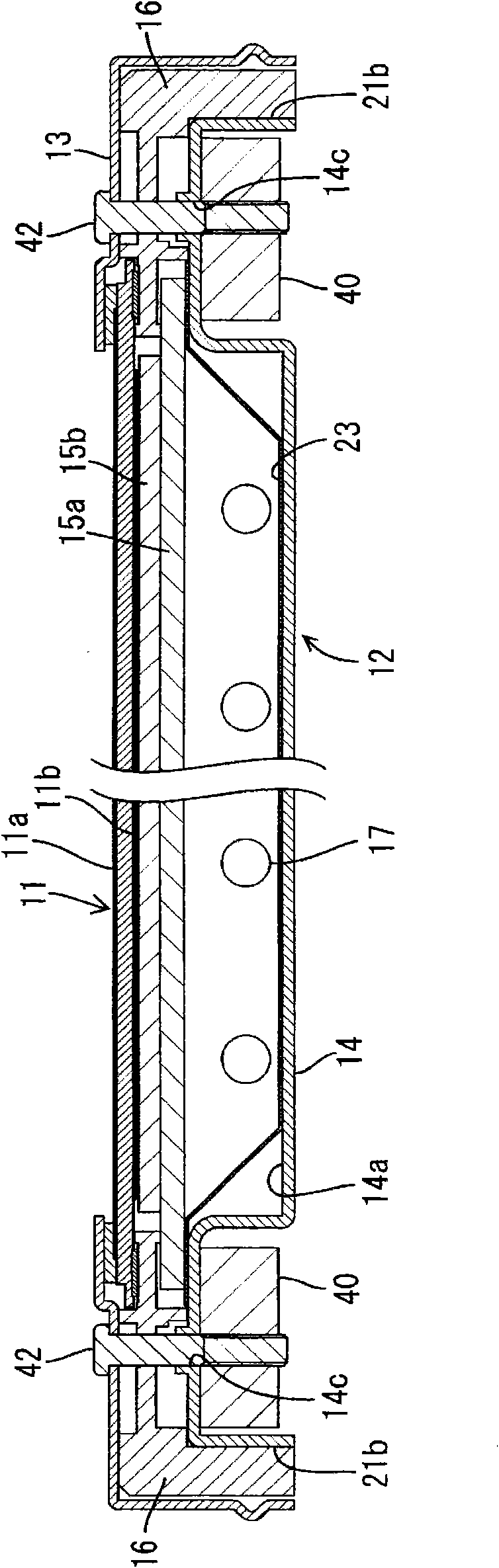
[0068] figure 1 It is an exploded perspective view showing a schematic configuration of a television receiver according to this embodiment, figure 2 yes means figure 1 An exploded perspective view of the schematic structure of the liquid crystal display device included in the television receiving device of image 3 yes means figure 2 A cross-sectional view of the main part of the cross-sectional structure of the liquid crystal display device along the short side direction, Figure 4 yes means figure 2 A cross-sectional view of the main part of the cross-sectional structure of the liquid crystal display device along the longitudinal direction, Figure 5 yes image 3 An enlarged cross-sectional view of the main part of the liquid crystal display device, Figure 6 yes Figure...

Embodiment approach 2

[0110] Next, use Figure 12 and Figure 13 Embodiment 2 of the present invention will be described. In this second embodiment, the outer edge portion is changed to have a double folded structure, and the rest is the same as the above-mentioned embodiment. The same reference numerals are assigned to the same parts as those in the above-mentioned embodiment, and repeated explanations will be omitted.

[0111] Figure 12 It is an enlarged cross-sectional view of main parts showing the cross-sectional structure along the short-side direction of the liquid crystal display device of this embodiment, Figure 13 It is an enlarged cross-sectional view of main parts showing a cross-sectional structure along the longitudinal direction of the liquid crystal display device.

[0112] The base 14 is formed into a relatively shallow box shape by forming a metal plate, which includes: a flat bottom 14a; 21a and the long-side outer edge portion 21b in the long-side direction).

[0113] Su...


PUM

PropertyMeasurementUnit
heightaaaaaaaaaa

Abstract

The invention provides an illumination device, a display device and a television receiving device. The illumination device (12) comprises a plurality of light sources (17) and a chassis (14) for housing the light sources (17). The chassis (14) is formed of a plate member and includes a bottom portion (14a) having a flat plate shape and an outer edge portion (21) formed at an edge portion of the bottom portion (14a) and having a folded structure (31). The outer edge portion (21) includes a core member (40) disposed inside the fold of the folded structure (31) and extending along the longitudinal direction of the outer edge portion (21). By forming the outer edge portion (21) to which such core member (40) is attached, the strength of the outer edge portion (21) itself is improved, so that deformation of the chassis (14) is prevented and a uniform illumination brightness can be provided.

Description

technical field [0001] The present invention relates to an illuminating device, a display device and a television receiving device. Background technique [0002] For example, since a liquid crystal panel used in a liquid crystal display device such as a liquid crystal television cannot emit light by itself, it is necessary to separately install a backlight device as an illuminating device. This backlight device is generally arranged on the back side of the liquid crystal panel (the side opposite to the display surface), and has: a base with an opening on the liquid crystal panel side made of metal; and a plurality of lamps (such as cold cathode tubes) accommodated in the base ). [0003] In recent years, in order to meet the demand for thinner liquid crystal display devices, the thickness reduction of each component of the backlight device has been carried out. Thinning of such components leads to a decrease in the strength of the components themselves, which may lead to a...

Claims


Application Information

Patent Timeline
Patent Type & Authority Applications(China)
IPC IPC(8): F21S2/00G02F1/1333G02F1/13357F21Y103/00
CPCG02F2201/503G02F2201/46G02F1/133308G02F2001/133314G02F1/133314
Inventor 山本修己佐藤保
Owner SHARP KK
Why Eureka
Try Eureka