Polarizing plate with adhesive and image display device

An image display device and image display technology, applied in the field of polarizing plates, can solve the problems of air bubbles around the printing height difference, uneven screen display, etc., and achieve the effect of inhibiting the mixing of air bubbles, inhibiting transfer, and not easy to fade

Active Publication Date: 2018-06-15
NITTO DENKO CORP
View PDF12 Cites 6 Cited by
  • Summary
  • Abstract
  • Description
  • Claims
  • Application Information

AI Technical Summary

Problems solved by technology

When the adhesive is applied to a transparent member with a decorative printing layer, air bubbles are likely to be generated around the printed step
In addition, local stress is applied to the image display panel directly below the printed step through the adhesive, and mechanical strain is generated at the edge of the screen, so display unevenness may occur at the peripheral edge of the screen.

Method used


Image

  • Polarizing plate with adhesive and image display device
  • Polarizing plate with adhesive and image display device
  • Polarizing plate with adhesive and image display device

Examples


preparation example Construction

[0091] In the preparation of the acrylic polymer, a polymerization initiator such as a photopolymerization initiator or a thermal polymerization initiator can be used depending on the type of polymerization reaction. The photopolymerization initiator is not particularly limited as long as it can initiate photopolymerization, and for example, benzoin ether photopolymerization initiators, acetophenone photopolymerization initiators, α-keto alcohol photopolymerization initiators, Aromatic sulfonyl chloride-based photopolymerization initiators, photoactive oxime-based photopolymerization initiators, benzoin-based photopolymerization initiators, benzil-based photopolymerization initiators, benzophenone-based photopolymerization initiators, ketals Photopolymerization initiators, thioxanthone-based photopolymerization initiators, acylphosphine oxide-based photopolymerization initiators, and the like. As the thermal polymerization initiator, for example, azo-based initiators, peroxide...

Embodiment 1

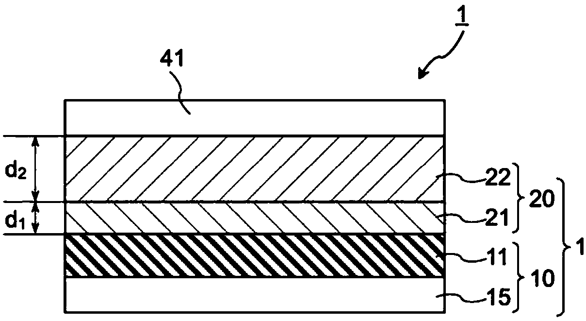
[0198] The above-mentioned pressure-sensitive adhesive sheet A1 was bonded to the exposed surface of the polarizer of the single-sided protective polarizing plate using a roll laminator. Furthermore, the above-mentioned PSA sheet K1 was laminated on the PSA sheet A1 using a roll laminator. Then, the above-mentioned cell-side pressure-sensitive adhesive sheet was bonded to the polycycloolefin protective film protecting the polarizing plate on one side using a roll laminator. In this way, a transparent protective film with a laminated adhesive sheet comprising the adhesive sheet A1 and the adhesive sheet K1 on the side of the exposed surface of the polarizer that protects the polarizing plate on one side and protects the polarizing plate on one side is obtained. A double-sided adhesive-coated polarizing plate with a cell-side adhesive sheet on the film attachment surface.

Embodiment 2~7、 comparative example 1~3

[0200] A polarizer with an adhesive on both sides was obtained in the same manner as in Example 1 above, except that the composition of the front side adhesive sheet attached to the exposed surface of the polarizer of the single-sided protective polarizing plate was changed as shown in Table 3. plate.


PUM

PropertyMeasurementUnit
thicknessaaaaaaaaaa
thicknessaaaaaaaaaa
thicknessaaaaaaaaaa

Abstract

The invention relates to a polarizing plate with an adhesive and an image display device. The polarizing plate (1) with the adhesive comprises a polarizer (11) comprising an iodine-containing polyvinyl alcohol film, a transparent protective film (15) attached to the first main surface of the polarizer and a front side adhesive sheet (20) which is arranged in a manner of being in contact with a second main surface of the polarizer. The front-side adhesive sheet is a laminated adhesive sheet obtained by laminating at least two layers of adhesive layers, and is provided with a first adhesive layer (21) which is arranged in a manner of being in contact with the polarizer and a second adhesive layer (22) disposed so as to be spaced apart from the polarizer. Preferably, the energy storage elastic modulus G '80 at 80 DEG c of the front side adhesive sheet is 1 * 105 pa or less, and the humidity of the first adhesive layer is preferably 150 g/m2 .24 hours or less.

Description

technical field [0001] The present invention relates to an adhesive-attached polarizing plate used for forming an image display device having a transparent plate or a touch panel on the front of an image display panel. Furthermore, the present invention relates to an image display device using the adhesive-attached polarizing plate. Background technique [0002] Liquid crystal display devices or organic electroluminescence (EL) display devices are widely used as various image display devices such as mobile phones, smartphones, car navigation devices, monitors for personal computers, and televisions. In order to prevent breakage of the image display panel due to impact from the outer surface, a front transparent plate (also called a "window layer"), such as a transparent resin plate or glass plate, may be provided on the viewing side of the image display panel. In addition, in recent years, devices having a touch panel on the viewing side of an image display panel have becom...

Claims


Application Information

Patent Timeline
Patent Type & Authority Applications(China)
IPC IPC(8): G02B5/30B32B27/08B32B27/06B32B27/30B32B27/36B32B23/08B32B23/20B32B17/10B32B7/12B32B33/00C09J123/20C09J11/06C09J153/02
CPCB32B17/064G02B5/3033C09J11/06C09J123/22C09J153/025B32B7/12B32B23/08B32B23/20B32B27/06B32B27/08B32B27/302B32B27/306B32B27/308B32B27/36B32B27/365B32B33/00B32B2307/726B32B2457/202C08K5/3492C08K5/3475G02B5/30G06F3/0412C09J121/00C09J133/00C09J7/20C09J2301/208C09J2301/312
Inventor 宝田翔泽崎良平保井淳
Owner NITTO DENKO CORP
Why Eureka
Try Eureka